Looking Back

Looking back at this semester and thinking about everything that I have learned is incredible. This class has introduced me to things I was unfamiliar with. It gave me the skills to be able to go about an idea in serveral different ways.

I thought back to some of the speakers that made an impact on what I learned. Even on the first week, when we had two speakers. The video call from John Horlick kicked off the semester. He had written a book on how 3D printing was really becoming more and more prevalent in business and our everyday life. This opened my eyes to Digital Making. I realized that things were constantly changing in how things were being made, but I did not realize how much of an impact innovation was actually making. Even though this presentation was mainly on 3D printing, I felt like it spoke for more than 3D printing. It showed that there is always a better or smarter way to do something. There are also many ways to achieve that goal and I believe that is what Digital Making entailed.

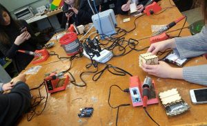
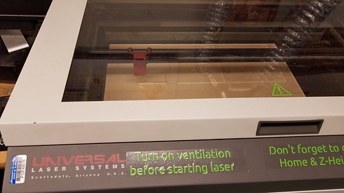
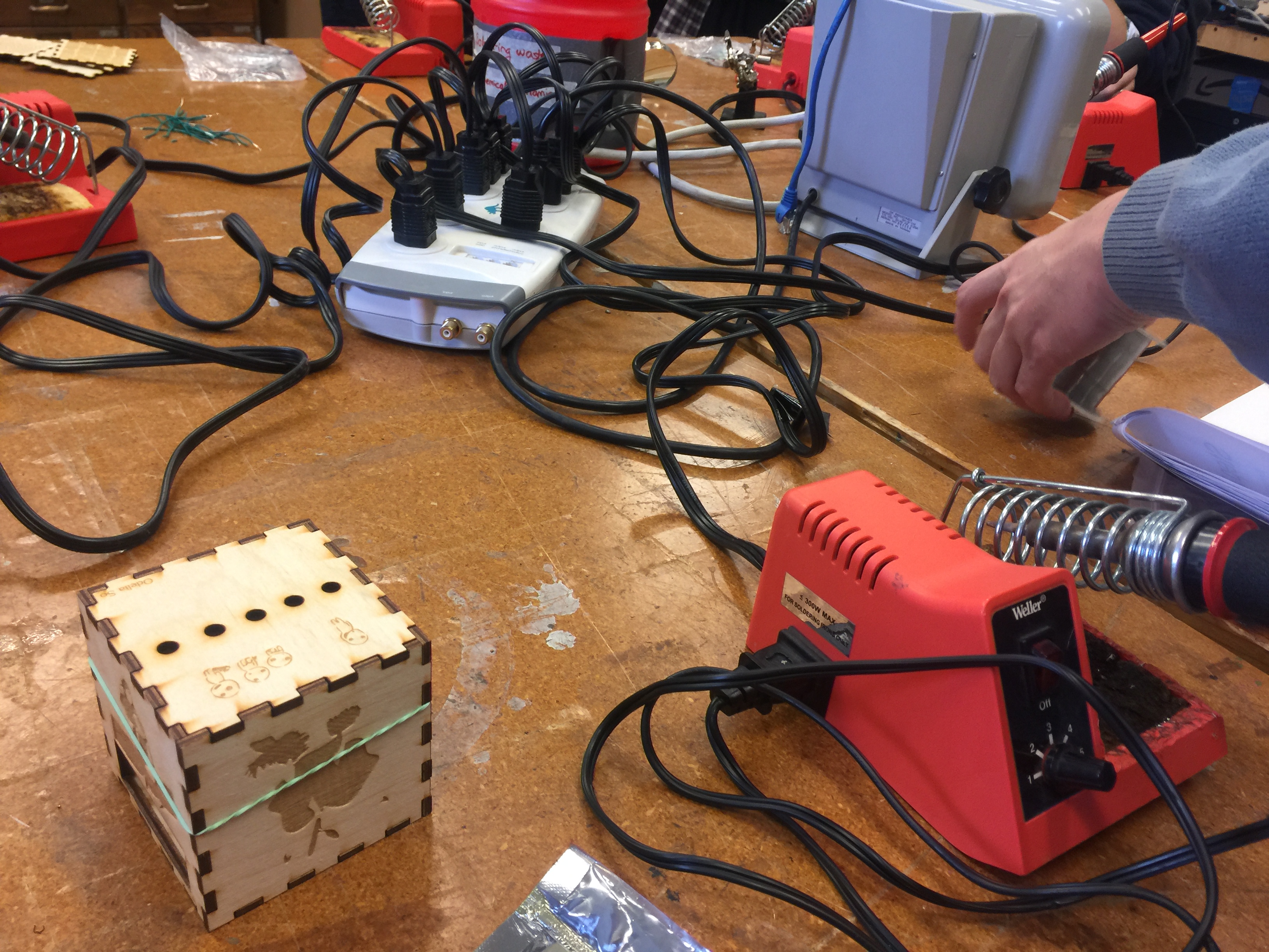
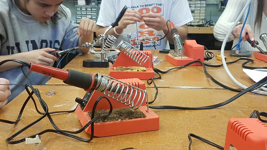
Most of everything I learned in this class, I had not been exposed to before. Something that was really foreign to me was coding aurduinos. I never thought I would mess with that. I had understood some of the code because I had dealt with coding before, but it had only been solely on the computer. I had never used a breadboard before. It was also awesome to see a product come together after our few weeks of class spent at the Fab Lab. Not only did we code Arduinos, but we lasercut wood boxes and soldered wires together. This was great experience that helped prepare us and our teams create and develop a product of our own for our final product.

Throughout the entire semester, I felt like each class taught us the skills to tackle a problem or accomplish a task that we would encounter as we did our final project. The guidelines of the final project were for you to create a project that solves a problem.

When I decided to take this class, I was hoping to get a better understanding of using different softwares. I took this class because I really liked the work I did in the lab and I wanted to be able to do more. I only had one class freshman year that I was taught a CAD software, Creo Parametric 3.0. Other than that, the only time I have had experience with other softwares was when I would help out with workshops at the MakerLab. I wanted to be able to learn them well enough to create things of my own.

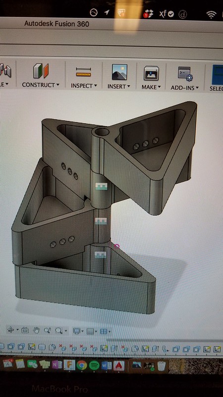
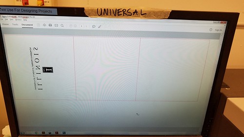
I feel like that expectation I had about the class was met. I was taught various softwares through a workshop type environment in class. That helped with figuring out where to start and what to look at to finish a design. Then I had to apply those skills I learned to the final project. It really tested me on how well I knew how to use them. I used Tinkercad for most of anything I did with the final project including the team logo. I was able to do it from my laptop in my free time. When I was looking at a folder I created on TInkercad and photos of designs I had sent my partners, I could see how my skill had improved throughout the semester. When I started, I did the basic shapes and a lot of things were uneven and had odd proportions. As I practiced, I was able to fix those problems and create more complex things. It was frustrating at points, but I was able to get my designs to how I wanted them to be.

This class opened my eyes to many things.  I was able to explore different ways of making I had never done before. I also, went through the product design process that made me explore every aspect of a design even if it is identifying what you can do yourself and when to seek outside help. In this class, I learned what I wanted to learn and more.

Research and Continuous Improvement

In this weeks session we had first started off with a quick presentation on scanners. I found it really interesting that we can scan with just our own phone cameras; they take pictures and stick them all together through a 3D mesh. They are created through triangles, so the more triangles the more resolution on the surface. The application that this feature could be done through is call Trnio and can be downloaded through an app store. After learning about scanning we began to work on our groups project again. Last week we had accomplished the main gist of how we wanted our product to look like, what components we would need and approximately how we would put it all together and into the 3D printed housing. However, in the last class we had only a general idea, which is why in this week’s class we had to go in more depth to understand more in detail what we would have to do and accomplish.

As none of us are engineers, we don’t have a solid understanding of how we should go about the project, which is why we had done a good amount of research to understand what components we would need as well as the placement of them. We had looked into various websites and videos, checking out the different tutorials and the ways other individuals had created a similar home security product. We had decided to use different tutorials and grab code from some of the already made products. Afterwards, we were able to receive all our components from Vishal and grabbed the rest of the components from the FabLab.

We then ended up meeting at the end of the week to work on the project together with our engineering friends. They had helped us with the installation of the Raspberry Pi and helped us with grabbing the correct code to run the system. We were able to put all the hardware together and plugged in the sensor accordingly. We had some difficulties with installing Twilio into the Raspberry Pi so we had tried to use a different method of Google Voice but that also did not turn out as we had expected even after adjusting many settings. Thus, we went back to trying to download Twilio, and to our surprise it could be done but we also had to download some other things to make it work. Finally, we tested the sensor with Twilio and the product worked! We still need to work on creating a way for the system to start on its own when plugging the power on and off so we will be doing more research on how to work that. During this time we had also started creating our 3D printed housing through Fusion 360 and we will begin printing it during the next class.


A reiterative process of trial and error

The progression of our ideas came to fruition this week as we heavily began idealizing and seeing how all of the parts of our design come together. The first half of this week’s class was allotted to learning 3D scanning from Ariel utilizing a handheld model. We then proceeded to scan our heads as well however, we learned that the scanner does not like dark surfaces and so we had to scan black hair with a phone light.

20170403_144847

The next half of class we were heavily involved in redefining our project’s components with an initial rough print. This taught us that we need to prototype fast and quickly due to the nature of how 3D printing is not perfect and it is a reiterative process in order to perfect a design. We continuously developed our design and got an idea of how to make these modules separate in the case if we want to add more or less at any given time. The Fusion 360 model below shows how we visualized our final product.

IMG1740895582

However, once we started printing, the holes did not line up correctly and sometimes the printer was having trouble with misalignment or if the filament ran out mid print as that happened to our initial prints.

20170405_150355

Then after another run through the printer we were able to narrow down the problems, address it and throw in another print. This one proved to be a much more successful model but it still did not stand up on its own which was cause for concern for us since we need it to be able to not only support its own weight but it needs to support, clay rocks, plants and moving water.

20170405_154052

Upon doing further research we found a great resource named “The Aquaponics Source” and it helped narrow down what type of plants, planting media as well as the conditions that are needed to keep our plants happy and healthy.

The next stages that I determined to be instrumental for the project is constructing the actual tank from 1/4″ acrylic sheets from the FabLab but they only had 1 clear one left and that was not enough since they were only 12″ x 24″ and so they are in the process of ordering more and it will come in about 10 days, which will hopefully give us time to cure and test our product. But I was able to use that one sheet and start dimensioning and designing the tank.

20170405_171649

20170405_173155

Our next step is to wait for all of the components we ordered to get here on time, which is the fish pump, tubing, finish printing the modules, as well as waiting for the acrylic to arrive and slowly put it together.


Team BCC Creations Designing and Prototyping Reflection

This week we mainly focused on our final project in regards to designing and prototyping. Prior to having group time Vishal had given us resources on the process of prototyping, and reminding us that this would not be the first prototype we would be creating but instead we would keep learning, rebuilding and growing form our prototypes that we create.

My group is Team BCC Creations; we are trying to provide college students with a peace of mind through a cheaper security alternative for their apartments. We have come to a conclusion that many students leave campus during breaks and during those times there are higher chances of trespassing. Thus, we have come up with a “cheap” alarm for a college student, as we don’t have the funds to be purchasing nice alarm systems that some of us may have at our parents’ homes. The alarm can be placed by any door and the alarm will detect whether the door is opened or not. If the door were to open the individual that enters has 5-10 seconds to shut off the alarm before it begins to ring and text the roommates of the apartment. Therefore, unsolicited entry will immediately cause the alarm to ring as well as notify the roommates of the apartment through text messages.

In order to create our alarm we will need a raspberry pi, Twilio, jumper wire, piezo, breadboard, ultrasonic sensor, battery pack, 3D printed housing and Velcro. During our group time we had created a poster that had a diagram of how the components would be connected to each other as well as a sizing guide so we could have a better understanding on how big the housing had to be as well as the alarm system itself. While drawing the diagram we had some concerns on how the parts would fit in but the breadboard gave us more leverage. Because we didn’t have the parts physically in front of us, we still need to approximate some of the components such as the piezo, because we may using a different alternative for the sound system. During class one of our group member had gone to the FabLab to check if they had any Bluetooth modules available for our use, but after speaking with a FabLab assistant we came to an understanding that we could use Twilio as cloud communication platform to send our texts instead of the Bluetooth module which we would need to have Vishal order. The raspberry pi has the capacity to use Wi-Fi and connect with Twilio, so we will still need to test it out but I believe that it could be a very suitable alternative.

After this weeks session we definitely have a better grasp as to how our product will look like, what it will be made of and where to get our components from. I can’t wait to see what we will be able to do in our next class once we have gathered all our components and have them physically laid out in front of us.

The diagram we had drawn in class.

Our ultrasonic sensor and breadboard.


Week 8: Skill Set and Soldering

This week at the FabLab we wrapped up the workshop sessions. My team, the white team did soldering this week. Before this week’s workshop, I’ve seen my dad solder wires together to improve “circulation” of the wires, so I already felt like I did have some knowledge in this area. However, in truth, this week was my first week in getting hands-on experience with it.

Soldering station

To be totally honest, out of all three workshop stations, my favorite was the laser cutting station due to my overall familiarity with the concepts of the machine, as well as the usage of the software. This week’s station was probably the most frustrating and difficult area for me. The combination of needing nimble, yet sturdy fingers to twist the wires together, the potent smell of the metals melting together, as well as the fragile and easily breakable wires made the whole process mentally straining. The constant need to be mindful of the positive and negatives of the LED lights, as well as the much-needed patience really took a toll on my attitude towards soldering, and by the end, I felt ready to give up and never touch soldering again. To add fuel to the fire, because of my twisting and turning of the wires, the connections constantly broke to a point in which some of the connections were unrepairable. Because of this turn of events, I was unable to successfully created the LED box that included the soldering of the lights and photoreceptors. Since I broke most of my connections toward the end of the class, I had no time to redo the soldering and was forced to create a prototype LED box with the breadbox and the Arduino. As much as I don’t like soldering, this skill is very important to have knowledge of. Thanks to CUC FabLab, I am now able to solder wires together (even if I’m terrible at it).

In the end, no matter how must frustration or hatred I had for a specific “step,” the workshops that we learned from were definitely really helpful in our group projects and will help us start finalizing what process and skills are needed for the project. Furthermore, not only did we gain three new skill sets to use but also gained insight to our abilities in each skill. By analyzing these interactions, we were able to tell which part of building our future project prototypes was our strong point and which was our weak point. For me, it was obvious that designing and laser cutting was my strong suit, while soldering was hands-down my weak suit.


Week 8: Last week at the Fab Lab

This week’s session marked our final week at the Fab Lab. Our time spent here was memorable and it’s sad to say that this is our last class time here, but the skills and know-how gathered here were quite memorable and are sure to last us quite a while. To conclude our 3 week journey, everyone participated in their last workshop to finish our light boxes. For me, it was finally time to code.

Having finished all the hardware aspects of the project, the last remaining task was the most integral to the box’s function: its programming. The Arduino itself is a powerful tool, but it cannot be used to its full potential without working with coding. The capabilities of a programmed Arduino are only limited by its user. Being an electrical engineering major, I’m required to have expertise in programming. Most of the programming that I currently do is in C programming, which is what the Arduino IDE (Integrated Development Environment) is based off of. I don’t really deal with the actual custom Arduino software much, however, so it was good to get some practice with this.

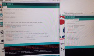
Arduino Software Application

We began with the basics, making a simple LED blink. Then we gradually moved on through the Arduino language to where we would be able to design a program that would make the light box behave as we wanted it to: as a light sensor with LEDs that activate accordingly to the level of light. The Arduino IDE is custom built for the various modules that Arduino produces, and as such their certain commands and implications available only to it and not in conventional C programming. We began creating slightly more complex circuits on a test breadboard preparation for the final step of the project.  We were allowed to play around and “hack” the programs provided to us so we could get a better feel of the software. This also allowed us to customize each of our light boxes to our preferences. We could select which LEDs would light up and in what order, the amount of light exposed to the sensor which would cause it to send signals to the LED, and so on. Relatively small adjustments, but those little differences were what allowed us to differentiate our final projects from each other. We finished compiling our code and assembled our boxes that we got to take home as a trophy for our weeks of work.

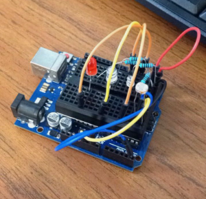
Test circuit for the final project

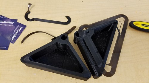
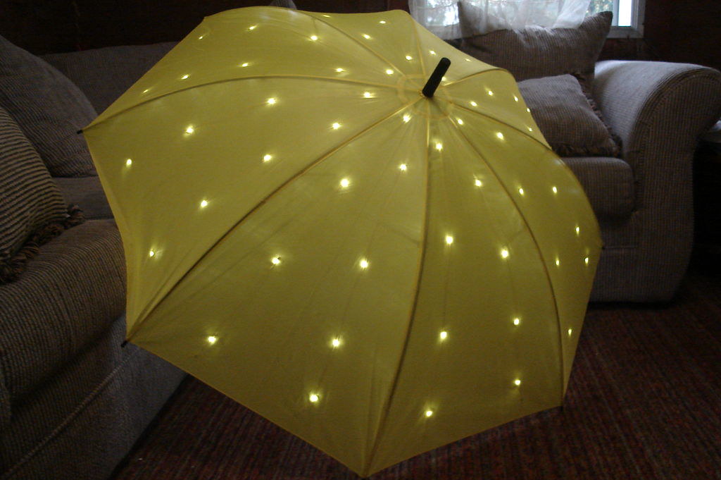
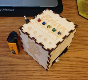
The long awaited finished product

It may have taken place over a few weeks, but our time spent at the Fab Lab seemed relatively short. I cherish the skills I’ve gained here and the memories of the fun I’ve had these past few weeks will last my lifetime as a maker(i.e. the rest of my life). We’ve come quite a way from our first session here, and our final class projects as well as our abilities as makers have certainly benefited from it all. The Fab Lab was such an amazing experience: I loved being surrounded not only by all the amazing technological tools and processes, but by other inspired and talented people as well.

Coding, Arduinos, and LEDS, Oh My!

As week 2 of constructing the light up box commenced, we took part in a coding and arduino workshop. Arduinos are electronics made of a combination of hardware and software tools. In our tool kit there was LED lights, an Arduino Uno, jumper wires, a breadboard, and a resistor. The first steps we took were to connect hardware to the Arduino Board.

We had to connect the different components together to create a circuit to allow for the flow of electrons or in other words electricity. I had trouble grasping the concepts at first, but when I started connecting the pieces together, things made more sense. Once we finished connecting the Arduino to the breadboard along with the LEDs, it was time to run some tests on it through software.

We used an Integrated Development Environment (IDE) software to upload a code, or a written text that tells the arduino what to do, onto the LED circuit that we had created. To test whether or not the code was successfully uploaded, we had to check if the LED light was blinking. I found it extremely frustrating trying to edit until the code worked, but once it was successful, I felt extremely satisfied. Afterwards, I had time to practice hacking the code and changing the time and frequency of when the LED would blink.

Overall I found the workshop to be a great first introduction to coding since I had never coded before. While coding is still a daunting skill, I am more motivated to learn it after having played around with it. I believe that coding is an incredible resourceful skill to have going into any industry.

I especially find it inspiration that companies and organizations are reaching out to children to teach and encourage them to code. Girls Who Code is a nonprofit organization dedicated in closing the gender gap in technology; they host after school clubs along with summer immersion programs for girls to learn coding and get exposure to the tech industry. Implementing coding into the fashion industry, Google’s Made with Code initiative allowed for girls to design a black dress with the help of designer Zac Posen and technologist Maddy Maxey.

Soldering + LED Lights = LIT

My Fab Lab experience just keeps getting more and more fabulous each time I visit. This week, my group had the chance to get our hands on soldering, which by definition is the act of fusing together the joints of metal objects by melting a filler metal. This is different from welding, a term I was more familiar with, in that it doesn’t involve melting of the actual workpiece, but rather just the filler metal which connects the wires. Our goal was to use soldering techniques to fuse LED lights and sensor wires together with the use of Arduino board to make a cool LED product. It was quite an intimidating process at first and I faced some challenges listed below, but gradually I was able to overcome some struggles I had and successfully create the final product–a series of LED lights that respond to the light sensor.
17269192_1534548909896760_405950736_o
17310721_1534548903230094_2065225234_o
Challenges I faced while soldering for the first time:

  1. Fear of getting burned (the soldering gun heats up to 350 degrees Celcius, which could cause a second degree burn with a single touch)
  2. Not having the wires stay connected although the filler metal has melted on them
  3. The smell. It wasn’t the best unfortunately.

This eye-opening experience certainly enhanced my interest in soldering and would definitely try again if I had the chance. Also, I looked up a few soldering products that look really neat. These are of course much more complicated projects than the one we did in class, but the basic technique is similar. Check them out!

LED Umbrella
FJXW1FUFEQ4B1PQ.LARGE

LED Ice Cube Clock
Screen-Shot-2016-03-18-at-17.57.41

Week 7: Arduino and Lights

This week, I got back my laser cut box and I was so excited on how my design came out.
The design that was laser cut.

Furthermore, this week the white group was assigned to the main lab in order to learn how to program an Arduino board. This was my first time actually seeing a computer board up close and I was definitely quite surprised by how it looked. Personally, I thought that it seemed quite fragile and easily breakable. However, it was quite sturdy and it could hold quite a bit of force. Along with the Arduino board, the following things were included: The Arduino packet FabLab provided.

Using the package, we connected power and ground to the board by connecting pins. By doing so it helps “power” and enables the user to correctly use the Arduino board. For example, we connected the pins and linked power and ground together so that later on we could “power” and enable the LED lights to blink and turn on. One of the steps to put together the blinking LED lights.

After assembling all the parts of the hardware, we had to “assemble” the software together and make the LED light blink by coding on the Arduino software. Here is one of the activities that we did:

The Arduino code in which sends a SOS through Morse Code.

This example was coded so that the LED lights would emit a Morse Code for
“SOS.” After coding for the LED lights, we had to add sensors. Personally, the sensor was the hardest part of building the hardware. Because the breadboard was so tiny, it was hard to find empty rows and columns to use for the sensor. However, with some help, I was successfully able to make the LED lights blink when I waved my hand over it. After completing and successfully doing so I felt such a sense of pride because, through my first attempt, I was able to successfully complete such a feat.The completed assembly for the workshop.

This week will be very applicable for our group project. Our group project is going to be a feedback droid in which there will be sensors, so learning how to connect the breadboard to the Arduino board through the pins. The coding as well using the Arduino software was very informative and will help us in the coding for our droid. I am excited to be using such new skills in my future group project. Next week, the white team will be soldering so that the LED lights will fit into the box well.

Week 7: 2nd Week at the Fab Lab (Laser Cutting)

Aside

For our second visit to the Fab Lab, each group switched stations to work on a different portion of our final project. This week, I attended the Laser Cutting session. Though the workshop is somewhat secluded towards the back of the Fab Lab, it certainly shines through as one of the more unique creative processes the Fab Lab has to offer (no pun intended).

In my last workshop, we focused on designing the physical circuit for our light-sensitive boxes. This week, we continued with moe hands-on work dedicated to making the appearance of the project aesthetic and to our liking. By using specifically designed software, we were able to create layouts for our boxes that we could customize. We first gained the template after entering our desired dimensions into an online resource, and then imported that file onto the lab computer software Inkscape to customize them. We were able to select images online to use as stencils for the panels. The images had to be completely black & white, as well as properly pixelated. The laser cutters are incredibly precise, and are able to stencil out wood portions with cuts of down to .001 m in width, resulting in flawlessly fitting pieces and stellar quality of silhouettes. One of the most amazing bits of all this, is that each person’s cuts only took approximately 20 minutes maximum, way faster than a conventional 3D printer. While it is certainly a sight to see something create out of nothing, some don’t realize that you can also achieve great designs by taking away from what you already have.

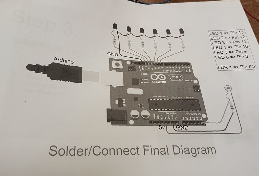
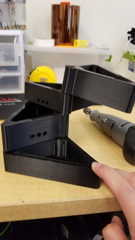
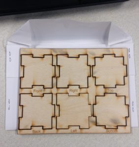
Smaller scale sample box pieces
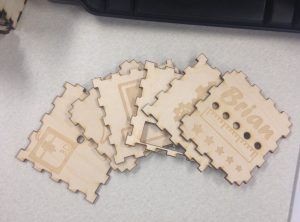
For my custom designs, I chose each side to represent a field of engineering/design as I am an engineering major. Four sides included images reminiscent of electrical, mechanical, and computer engineering, as well as architecture. The underside of the box features a 3D printer silhouette as well as that of a laser cutter, the two main methods of design that my group will probably use in our final project. The remaining side just has my name with a special measurement system composed of a ruler image and different sized stars to represent the brightness of the LEDs.

My pieces

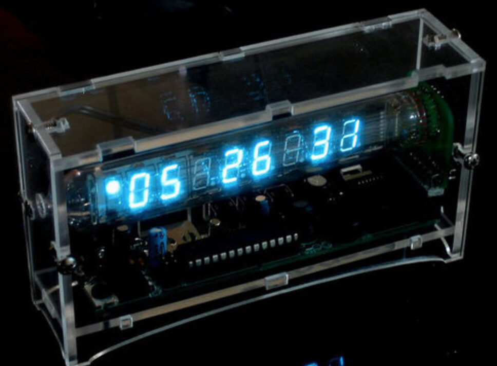
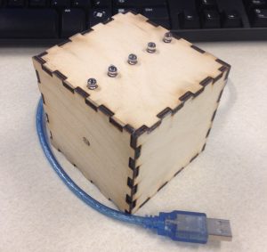
Sneak peek of the completed project

Now that I’ve completed both the physical portions of the workshop, I’m excited to take part in the coding session next week, where we will program the Arduino with the desired code to allow it to respond as we want it to. I’ve thoroughly enjoyed these Fab Lab sessions not only because we get to create a custom project for ourselves to keep in the end, but we also get to see multiple types of engineering and designing intertwined (specifically electronics, mechanics, and programming) into a single project. It’s been a fantastic experience to work with all these different processes, and I’m hoping that we can incorporate every one of them into our final project.