Team MakerLax Tie Assistant Project Reflection

Overview:

The MakerLax Team consists of three members with very diverse backgrounds. Brian is a freshman majoring in electrical engineering, Peter is a senior in advertising, and Chase is a senior in business. Having three strongly uncorrelated majors allowed us to experience a wide range of perspectives throughout the semester. While at times one of us were unfamiliar with a certain part of the making process, the others would step in and help fill the knowledge void.

Motivation:

While our initial ideas proved to be either too complex or out of the scope of this course, we ultimately decided on our final topic based on an article Vishal shared during one of our classes. The article focused on creating a “How Can We?” statement, which essentially stated that, in order for an idea to become a reality and a finished product, it must first meet three criteria. First, the idea needed to be narrow in its scope. Users should be able to understand the capabilities and capacity of the product without needing an extensive manual to guide them. Next, the idea should be local in its presence, meaning that the product should serve some type of purpose that fulfills a need in the surrounding community. By doing this, the creators will already be familiar with the problem and can devise more intuitive solutions. The final requirement for this product was that the answer needed to be realistic. Users cannot be expected to have advanced knowledge of programming, for example, in order to fully utilize it. Drawing from these three requirements, we ultimately decided to gear our making efforts towards aiding students in preparing for professional engagements, such as interviews, career fairs, or networking events.

Prototypes:

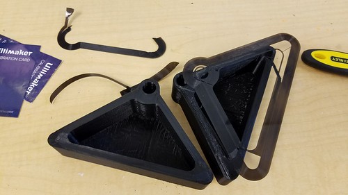
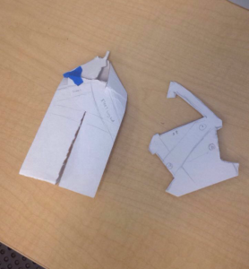
The very first crude prototypes that we created were paper models. They were quickly fashioned to act as both visuals, as well as to test different shapes for our design. After we decided on one, we recreated that form in Fusion 360. Our very first print was only meant as a test for the shape that we decided to implement. Initially, we considered making the design modular in some way. Either by adding tabs for the parts to lock into, or by creating a “puzzle piece” design. Eventually, we decided to keep the design as a single unit. Afterwards, we shifted to TinkerCAD as we believed it would better for our purposes. We then printed more models to test various clip designs. After we found a suitable one, we moved to testing. The size and shape seemed fine, but it was a bit cumbersome to wrap the tie around the sturdy print. It was this that caused us to move on to the semi-flex filament for our last design. After reprinting the last model in semi-flex and testing it, we found it satisfactory and used everything we gathered to create the final product.
Final Product:

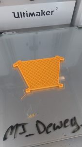
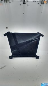
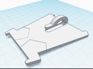
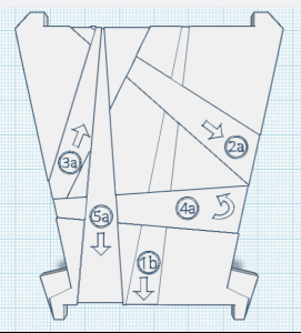
Our final product was, at first, our second to last model. After producing and testing the semi-flex model, we thought it was suitable enough to be our final design. However, somewhat last minute, we decided to improve upon it further. We decreased the dimensions, and redid the shape to make it more versatile. Physical features such as grooves and numbering were added to act as guides and “mini-instructions” to improve the ease of usage. It still is not necessarily perfect, and the print itself did not turn out that well, but it is quite an improvement on the original.
Features & Benefits:

Our final design has a thin and sleek profile, making for easy storage. It can easily fit within a pocket or portfolio. The flex material makes it very malleable and not very prone to breaking. This also allows one to utilize it with ties of varying shapes and sizes, and work it with ease. The clip is barely noticeable and and the physical structure of the design allows it to hold a tie snugly while at the same time allowing for easy removal. The indentations in the front face of the model are of different depths, allowing a user to feel around for the different steps. A number and arrow system are also engraved into the face that coincide with the instruction manual. Aside from allowing one to tie a tie around oneself, it can also be used to store a premade tie, in the event that the user foresees a circumstance for it.

User Feedback:

Overall, we found user feedback to be incredibly helpful during our prototyping phase. We had both in class feedback along with feedback from students outside the classroom. During the sessions, we were able to observe how our products were used the and difficulties that occurred. One student said, “I suggest adding instructions or some kind of step-by-step process to make using the product easier.” We took their advice and created a pamphlet as part of the packaging and adjusted the clip size and indents on our original prototype.

Future Improvements

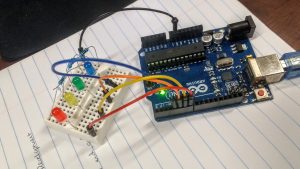
We hope to utilize more materials in future prototypes. Semi-flex filament was different to handle and took the 3D printers multiple tries to print out our prototype, so we hope to test different types of semi-flexible materials. One feature would be to have a collapsible, modular format. The benefit would is that the user can easily remove the product once they had completed tying their tie. From the user feedback, the other suggestion we were given was to incorporate electronics into our design. The product would have an LED guidance where different sections would light up green to guide the user to tie the tie. The LED guidance would require coding and implementing a small arduino and a battery into the product.  
Takeaways:

After the conclusion of this project, our team came away with three main conclusions from the experience. Firstly, it was incredibly satisfying to see our weeks of efforts and labor culminate in a working and usable model. One of our team members who previously was unfamiliar with how to tie a tie was able to learn how, with the guidance of our product. After seeing it be put to use, we can say with complete certainty that our efforts proved worth it. Additionally, we learned that rapid prototyping is critical to the making process, and to creating an effective final product. We spent the majority of our initial efforts attempting to make the perfect first prototype, when in reality the majority of our progress came upon the third and fourth iterations. Similarly, our team realized the immense importance of receiving user feedback. While we had certain connotations of the direction we wanted to pursue with our product, obtaining feedback from users that were unfamiliar with the making process gave us great insight as to what the average user would actually prefer.

Slide Presentation:

https://docs.google.com/presentation/d/1IPbJ5ryCkPmgwZ3aqKYncMZNeR6uIaXsuPVW9Mw8MWc/pub?start=false&loop=false&delayms=3000

Product Testing

We are at a time in the semester where everything is coming to an end. This is also a time where everything on our product is coming together. Throughout the semester we have developed a product through rapid prototyping. Now we have reached the point of product testing. This will help teams figure out what they need to fix to either make their product better or appeal to more consumers.

It has been a journey for my team to get to where we are now. Last week, we had a small prototype of our product. It was functional. As we held it in our hands, we realized what we could improve. We thought we needed a bar at the front of the device to keep it from letting the sliding mechanism from sliding out. We also thought the sliding mechanism could be longer. Besides the improvements we were able to notice as a group, we met with other groups to get their feedback. This was very helpful to get their feedback. Since others teams are going through the same process of developing a product, they have helpful insight. One team told us that they felt some of the sides need to be made thicker. If we increase the sides then we are less likely to have weak points in our design. Other than those comments, the teams liked our design and that we were going to use the Flex material to the sliding mechanism.

After getting that feedback, my team and I went to work on making changes to our design. We essentially made everything thicker. We also added a bar to the edge of the base. This is to prevent the sliding mechanism from sliding off. In order to make this adjustment we had to make the sliding mechanism into 2 parts. The handle on the sliding mechanism is separate from the entire mechanism. We will just need to glue those two parts together. I thought this would be fine because the handle does not need to be very strong since it does not come into direct contact with the door.

These adjustments got us closer to our final design. Although since we did make more adjustments, it did set us back on properly testing our product. We should be able to put our print on again to have it printed in the flex material. Then we will be able to do proper testing!

Idea Coming Toegether

My team and I had a lot of things to get done this past week. We did learn a lot from asking other people what they thought of our design and implementing those thoughts into our design. Although this did put us more towards the beginning of the design development process. Needless to say we had a lot to accomplish.

Our time in class was dedicated to working on our product. My team and I talked about our feedback from others and were able to come to an agreement and create our design on Tinkercad. We came about this by deciding what parts of our product needed to be finalized before we moved onto the next part. Instead of worrying about the material design and testing all at once, we decided one thing at a time. We thought we needed to at least finalize a design.

We had gone through a lot of designs. Our final design will be attached to the side of the door and have the ability to slide out to ajar the door and then slide back in and then let the door close. SInce it will be positioned horizontally on the door we do not have to worry about it moving around too much without the user moving it. Also, the moving part will have a handle to make it easy to move the device in and out.

Now that we had finalized we put it on the printer to see if the dementions were correct. In the time our product was printing, we discussed on what materials we think would work best for our product. Our main concern was trying to find a material that would hold up to a door slam. We needed something to absorb the shock a little bit. We thought the base part that is attached to the door could be made out of PLA since it does not come in direct contact with the door. For the sliding part, we think using the material Flex will be the best because we can print it thick and it has some give to it.

We did do trials in class. We wanted to see if the prototype we printed in class would hold up to the door in the MakerLab. Sadly, the door won after a few trials. But we intend to increase the size and density of our product and use the correct materials for the real trials!

Prototype Testing: The Breaking Point

After our abrupt change in product and design last week, we used the time between classes to rethink and design our door stopper in order to have a prototype ready for print by this week’s session. After debating several designs of various operations and complexities, we settled upon a simple sliding motion. Although the majority of the session was waiting for it to print (we elected to print the prototype as a scaled down version in light density to be economical with resources), we were able to execute several tests once the printing and assembly process was complete.
We used the doors in the lab, as they are relatively heavy and have a tendency to slam; they also are auto-locking, and therefore would be one example of a place in which our product would be put to use. Since we have not yet decided upon the best way to fix our door stopper to said door, I held it against the door for each of the trials, attempting not to interfere too much with the velocity of the door. Despite its lesser size and low density, our design held up quite well. Ben wanted to test how much pressure it could withstand, so he began to place more and more pressure on the door – moral of the story: our door stop cannot withstand Ben Chin’s entire body weight being thrown against the door.
Moving forward, we plan on printing our door stop on a larger scale (about 2x larger) to spread pressure out and prevent snapping from a concentrated pressure point. Furthermore, we are going to add a piece in order to prevent the sliding piece from sliding entirely out of the bracket, as was possible in the original prototype (this could result in loss of the sliding piece, as it is not fixed to the rest of the product.) We are excited about this next edition, and hope that it will prove a solid base for our final product.

Seeking Advice

Last week, my team and I still had a lot to decide. After the previous week of completely changing our product idea, we had a lot of ground to make up. We were basically starting from scratch. We still did not have a clear product idea and wanted advice on where to go. So our goal by the end of class on Monday was to make a plan. We decided on a design. Our design was to have on piece that had a notched design attached to the door. Then we would have a moveable part that moved in the notched part to slide out to ajar the door and slide back in when you would want to door to close. We were unsure on what materials to choose, but we were thinking of using thick metal and coving it in a rubber resin.

The next day we went over to the Fab Lab seeking advice. When we got there we showed them our plan. We went back and forth on what would work and what would not work. We decided that using metal was not the way to go. It in the end would be very expensive and we would probably have more luck with either wood or plastic. The problem we might have with wood is that we might put out more effort and time than necessary. They suggested that we us CAD software to try different variations and we could always print it and see how or design works. Going to the Fab Lab was very helpful because we had a better idea of where to go with our design!

Now we have to figure out exactly what we are going to do. We have thought of two designs so far that we have run through this past week. One design was like the original slide out the side of the door. Another design we had was to have something we could slide a bendable material to ajar the door from the top. These ideas are similar, but go about ajaring the door from different sides of the door. Currently we have not decided on which design we will choose, but hopefully by class on Monday we have made that decision. I think it is better that we have thought of different options to go about solving our problem instead and drawing a blank. This is a process we are consistently going through.

A reiterative process of trial and error

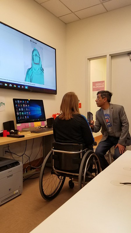
The progression of our ideas came to fruition this week as we heavily began idealizing and seeing how all of the parts of our design come together. The first half of this week’s class was allotted to learning 3D scanning from Ariel utilizing a handheld model. We then proceeded to scan our heads as well however, we learned that the scanner does not like dark surfaces and so we had to scan black hair with a phone light.

20170403_144847

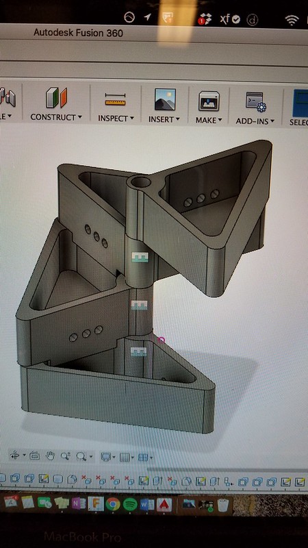
The next half of class we were heavily involved in redefining our project’s components with an initial rough print. This taught us that we need to prototype fast and quickly due to the nature of how 3D printing is not perfect and it is a reiterative process in order to perfect a design. We continuously developed our design and got an idea of how to make these modules separate in the case if we want to add more or less at any given time. The Fusion 360 model below shows how we visualized our final product.

IMG1740895582

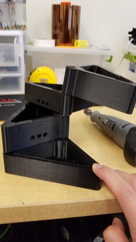
However, once we started printing, the holes did not line up correctly and sometimes the printer was having trouble with misalignment or if the filament ran out mid print as that happened to our initial prints.

20170405_150355

Then after another run through the printer we were able to narrow down the problems, address it and throw in another print. This one proved to be a much more successful model but it still did not stand up on its own which was cause for concern for us since we need it to be able to not only support its own weight but it needs to support, clay rocks, plants and moving water.

20170405_154052

Upon doing further research we found a great resource named “The Aquaponics Source” and it helped narrow down what type of plants, planting media as well as the conditions that are needed to keep our plants happy and healthy.

The next stages that I determined to be instrumental for the project is constructing the actual tank from 1/4″ acrylic sheets from the FabLab but they only had 1 clear one left and that was not enough since they were only 12″ x 24″ and so they are in the process of ordering more and it will come in about 10 days, which will hopefully give us time to cure and test our product. But I was able to use that one sheet and start dimensioning and designing the tank.

20170405_171649

20170405_173155

Our next step is to wait for all of the components we ordered to get here on time, which is the fish pump, tubing, finish printing the modules, as well as waiting for the acrylic to arrive and slowly put it together.


Final Projects in the Making

For this week, we delved into the last stretch of the course: our Final Project. Each group some sort of solution to a problem of their choosing; big or small. The issue or solution does not necessarily have to be 3D printing-related, but simply portray the aspects of design and making that we have learned over the course of the semester. Although, most of the final projects do include 3D printed models to some degree. This week, we began the first stage(s) of our projects.

My team and I, the MakerLAX, decided aimed to resolve an issue that was felt by many college students and other young adults: tying ties. As one gets older, they will have to attend more and more formal events and gatherings, and as such will require more formal dress. The tie is an integral part of formal attire, but is notoriously difficult to prepare for the first time, as well as long after. It may seem like relatively simple task, but getting accustomed to tying a tie as well as all the different knots that once can choose from takes time. This combined with the fact that most young adults only really have to wear ties from time-to-time and not on a daily basis, makes learning the ins and outs of tying one somewhat difficult. I personally require assistance from someone who already has gone through the whole process of learning how to tie a tie, or watching an online tutorial whenever I find myself needing a tie. While this may not be an inherently big problem, it can certainly be helped.

The premise behind our solution is to create a sort of “tie-helper”, as in, an object about the size of a small paperweight that can act as a guide for a person to use to tie their tie. We have found remnants of what appear to be previous attempts at creating such a product, but they were either flawed or never really reached production. https://www.youtube.com/watch?v=D3tkWcp3wK4 Our group is aiming to create a design that can be mass-produced or even printed at home. The idea as it stands so far is to print a model that is inscribed with numbers and/or pictures of instructions on how to tie a specific knot that has yet to be chosen. After finishing the knot, the object can be easily separated from the tie and the tie will already be tied around the neck. In class, we presented our idea to the rest of the groups and were given feedback. We also created some crude models of possible designs, which could be considered our initial prototypes. From here, we will be creating and testing new models to perfect for our final iteration. We’ve all learned a lot these past few months in Digital Making; I am really looking forward to putting it to good use, as well as seeing what everyone else comes up with.

Paper Prototypes

Team BCC Creations Designing and Prototyping Reflection

This week we mainly focused on our final project in regards to designing and prototyping. Prior to having group time Vishal had given us resources on the process of prototyping, and reminding us that this would not be the first prototype we would be creating but instead we would keep learning, rebuilding and growing form our prototypes that we create.

My group is Team BCC Creations; we are trying to provide college students with a peace of mind through a cheaper security alternative for their apartments. We have come to a conclusion that many students leave campus during breaks and during those times there are higher chances of trespassing. Thus, we have come up with a “cheap” alarm for a college student, as we don’t have the funds to be purchasing nice alarm systems that some of us may have at our parents’ homes. The alarm can be placed by any door and the alarm will detect whether the door is opened or not. If the door were to open the individual that enters has 5-10 seconds to shut off the alarm before it begins to ring and text the roommates of the apartment. Therefore, unsolicited entry will immediately cause the alarm to ring as well as notify the roommates of the apartment through text messages.

In order to create our alarm we will need a raspberry pi, Twilio, jumper wire, piezo, breadboard, ultrasonic sensor, battery pack, 3D printed housing and Velcro. During our group time we had created a poster that had a diagram of how the components would be connected to each other as well as a sizing guide so we could have a better understanding on how big the housing had to be as well as the alarm system itself. While drawing the diagram we had some concerns on how the parts would fit in but the breadboard gave us more leverage. Because we didn’t have the parts physically in front of us, we still need to approximate some of the components such as the piezo, because we may using a different alternative for the sound system. During class one of our group member had gone to the FabLab to check if they had any Bluetooth modules available for our use, but after speaking with a FabLab assistant we came to an understanding that we could use Twilio as cloud communication platform to send our texts instead of the Bluetooth module which we would need to have Vishal order. The raspberry pi has the capacity to use Wi-Fi and connect with Twilio, so we will still need to test it out but I believe that it could be a very suitable alternative.

After this weeks session we definitely have a better grasp as to how our product will look like, what it will be made of and where to get our components from. I can’t wait to see what we will be able to do in our next class once we have gathered all our components and have them physically laid out in front of us.

The diagram we had drawn in class.

Our ultrasonic sensor and breadboard.