Putting it All Together

For the final week in the Fab-Lab, we were tasked with figuring out soldering which wasn’t that difficult and a lot of fun. We utilized a tool that basically would melt the solder and that melted piece of metal would lock in the joint that we were melting it onto.

From there we created an intricate group of LEDs that would serve as the LED structure for the main part of our final box product that we were putting inside our wooden box.  The soldering instruction was fantastic as they told us exactly how to use it and more importantly how to use it safely. The only real difficulty with soldering was making sure that when you soldered it looked clean. Which, unfortunately, I was not very good at doing at all.

IMG_0579

Pictured above is the soldering device that we used during the demo. The main component is the device that looks like a pen. That device’s tip would heat up and allow us to melt pieces of metal called solder onto different objects that would link it all up together. The nob on the device controlled heat but we didn’t touch that at all. Then most importantly you should always clean the solder pen off on the sponge after using it so no leftover pieces stick onto the solder pen itself.

IMG_0595

Pictured above is the final product that we worked up too. Unfortunately, I was unable to finish my own box but I was able to get all the LEDs inside the box! The reason for me not being able to finish the whole box was because I couldn’t get the puzzle pieces to match correctly. only when I had hot glued most of the sides together did I realize that I actually glued them in the wrong order, unfortunately. This honestly kind of sad when I ended up with it but I think I might return to try and redo the whole box now that I know how to make one myself!

Overall, the Fab Lab experience was incredible. I learned a lot about making things and gained a lot of confidence for the future whenever I need to make something that involves not only hardware but also the software as well. I’m looking forward to being involved with Fab Labs in the future for sure.

Week 7 Summary: Building on Our Skills in the Fab Lab

In Week 7 of the Digital Making Course, our community of Makers once again ventured over to the Champaign-Urbana Community Fab Lab. Similar to week 6, our class broke into our three groups to work on the next rotation in making the Blinker Boxes. However, since we were already familiar with the layout of the building and the resources available to us at the Fab Lab, we were able to hit the ground running. Once again, our three groups were split up to working on Coding with the breadboard and Arduino, soldering the electronics, or designing the press-fit boxes for laser engraving and cutting.

Our time in the CUC Fab Lab serves many purposes. First and foremost, it provides us the opportunity to practice skills that can help us with our own making endeavors. It is especially helpful for our project groups to develop a diversified skill set that we can utilize on our semester projects. The workshops at the Fab Lab also familiarize us with the technologies and physical tools available to us. Learning from the staff also helps us get a feel for the greater Maker Community and hearing about their personal projects helped us understand their skill sets and how each of them may be able to help with our projects. Finally, spending time in our own Maker Lab, the Fab Lab, and with all the staff and volunteers gives us a better idea of the Maker Movement that is revolutionizing businesses across the nation and around the world.

Supra

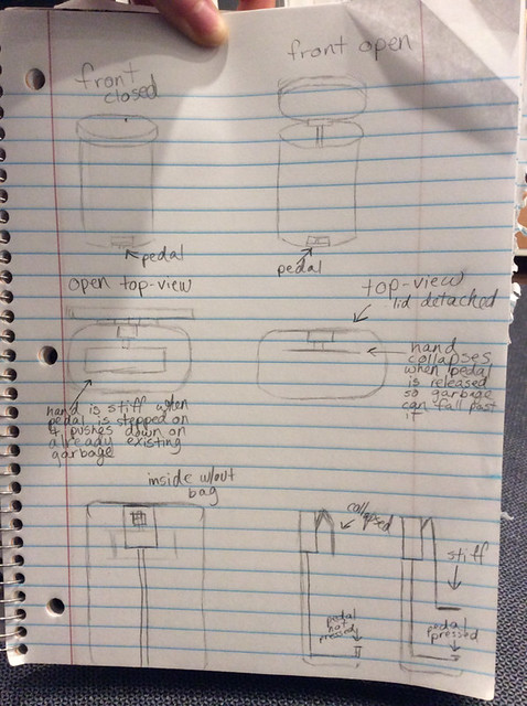
Team Supra’s Concept

As we keep going through the semester, we are rapidly approaching the design and prototyping phases of our semester projects. All of the project teams are refining their “How can we” statements while defining the actual problem they are looking to solve. Our first project idea submission was due on Wednesday of Week 7. To give you an idea on some of the concepts the class is working on, Team IJK is trying to help college students decrease stress by using indoor gardening. Team XNihilo is attempting to have busy professionals or college students drink more water. The MakerLAX is hoping to “help teenagers, young adults, and anyone else who struggles” tie a tie properly. Team Zerott is trying to improve patient satisfaction at hospitals. In Week 8, the project groups will be moving forward based on the feedback they have received. Once again we will be submitting our “How can we” statements, but this time we will include a concept details, key components of the solution, the capabilities of team members, outside resources for skills and fabrication tools, and any information resources identified.

Odelia Code

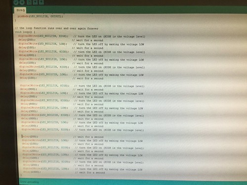
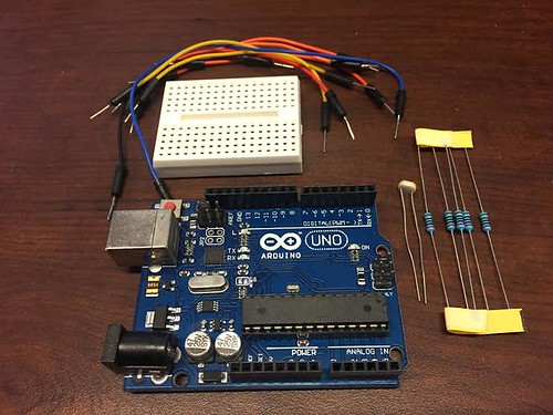
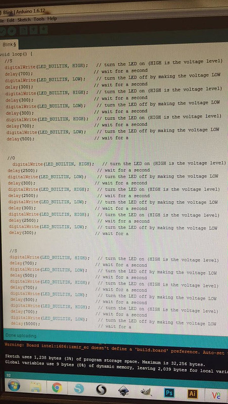
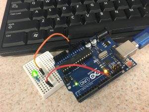
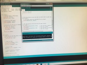
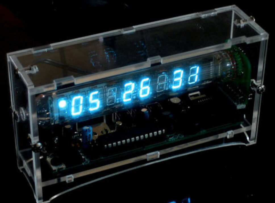
Odelia spent this week in the computer section of the Fab Lab code the Arduino for the Blinker Box. Odelia said, “This was my first time actually seeing a computer board up close and I was definitely quite surprised by how it looked. Personally, I thought that it seemed quite fragile and easily breakable. However, it was quite sturdy and it could hold quite a bit of force. Along with the Arduino board, the following things were included.” After setting up the circuit and trying to adjust the code, she found working with the light sensor was the most difficult part of the lesson. I think many would agree, as the range of values corresponding to which LED flashed depended on the specific sensor and how bright the part of the lab you were sitting in was.

Chase Soldering

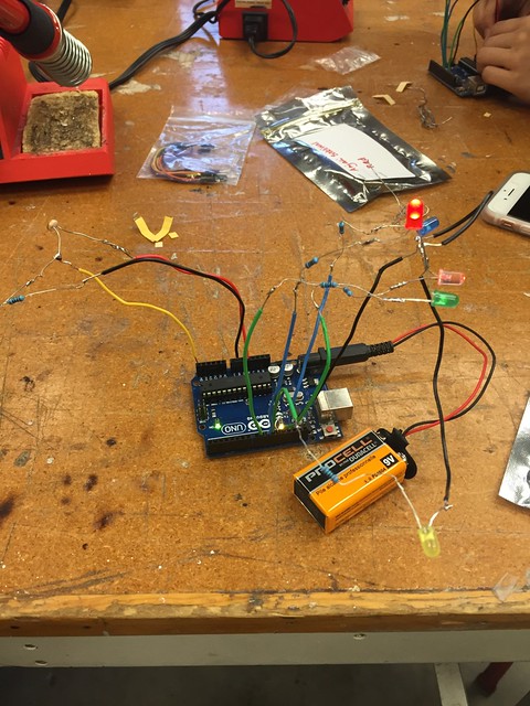
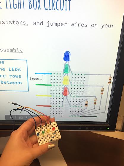
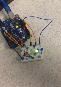
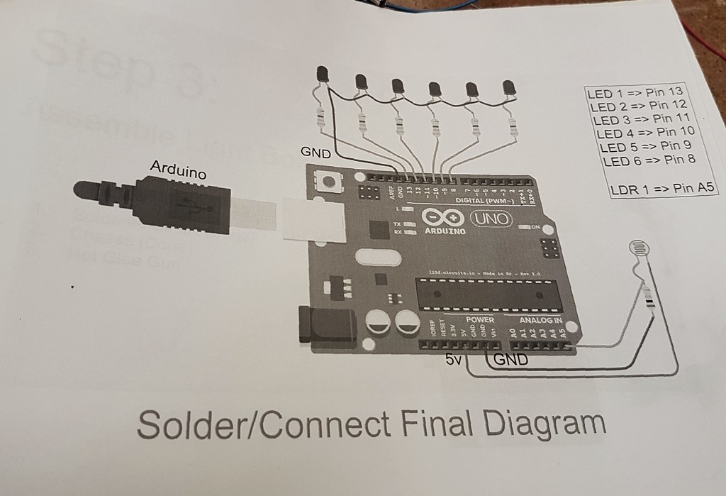
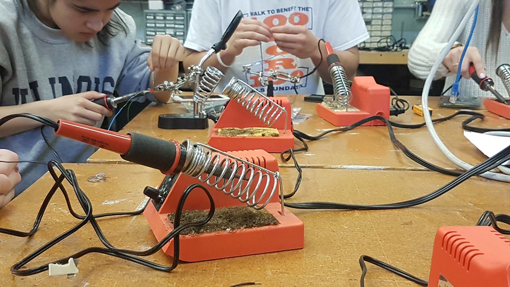
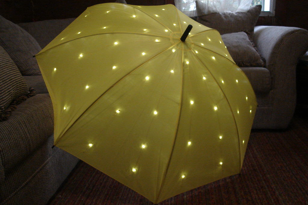
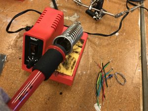
Chase spent the class time in the electronics section of the lab soldering his LED’s together. Reflecting on the class , said “the instructional course ultimately proved to be very time consuming and required incredible delicacy, there is little doubt in my mind that this is a crucial tool in any maker’s arsenal of building tools.” For many in the class, this was their first experience with soldering. However, we all were able to pick up on tips and tricks such as using the “helping hands” or tape to hold wires down while soldering multiple pieces together. By the end of class, Chase and his group mates were able to wire the LED’s and sensor into the Arduino he programmed in Week 6 and the LED’s flashed as planned! Finishing off his post, Chase, like many, said he hopes to “incorporate soldering in some capacity” into the final project.

Kenny Design

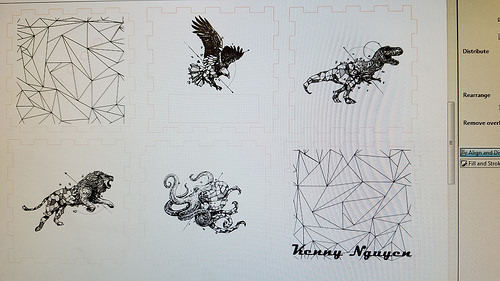
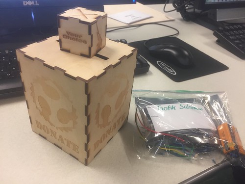
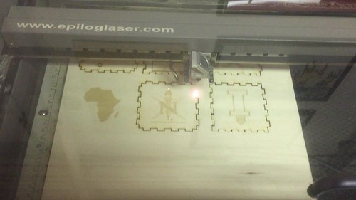
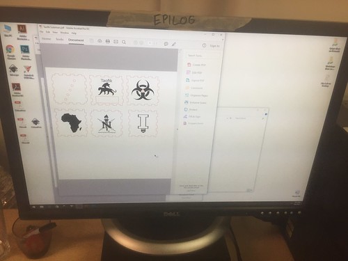
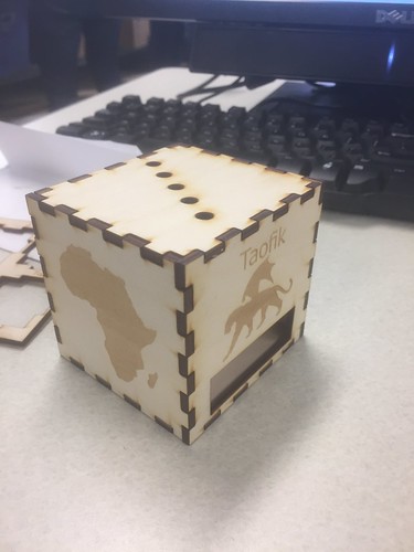
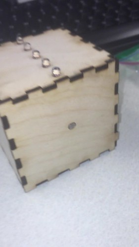
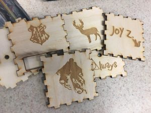
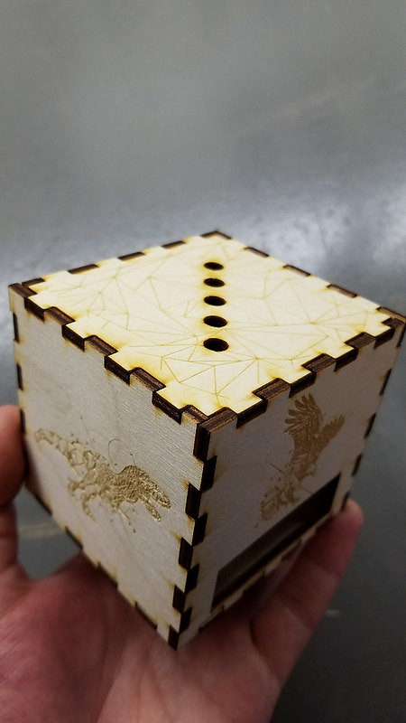
The final phase of the Blinker Box is the making the press fit box. Kenny wrote about using the free Inkscape software to design his box. By taking images from the Internet and vectoring them using the Trace tool, the images became compatible with the laser. Kenny chose artwork from one of his favorite designers to put onto his box. Once it was finished, he said, “It was very rewarding to be able to see something you design on a computer come to life in a matter of minutes. There was something satisfying from watching it go back and for until your vision comes true.”

Kenny Box

All of our blinker boxes are coming together as we build on our skills at the Fab Lab. Week 8 will be the last class session in the Fab Lab but many of us will be back to work on our projects. Happy Making!


Week 7: Bright Coding Skills, Brighter LEDs

Entering the Fab Lab, I was excited to know what to do next. I really enjoyed the collaborative atmosphere and the hands on work making things. As we began class, I was told that I would be doing coding in the computer lab with Arduinos. My heart jumped for joy when I was told we were coding. It was a flashback to high school. When I was in high school, I took all the computer science classes there were until AP Computer Science and even the game design. There, I was the only girl among a class full of men who learned how to code in Java and Flash. Despite being consistently told that I wouldn’t be good at coding because I was a girl. I worked my little feminine heart out to prove them wrong and within a few months, I was coding circles around them. These classes began my interest in the IT world. I was almost a computer science major before I realized that I love business just as much. With ISIT being basically a harmonious mix between the two, it was the perfect match to me. Although I was happy to be an ISIT major, I didn’t expect to code, so I was happily surprised with this workshop.

Arduino, Breadboard, jumper cable, resistors,and  ultrasonic distance sensor (LEDs not pictured)

unnamed (1)


SOS Code

kjkjn

SOS Blinking Demonstration

Animated GIF  - Find & Share on GIPHY


When beginning the workshop led by Brandon Rice, we were told what we were going to be learning. The goals of this workshop was to learn about Arduinos and the Arduino process, interface an ultrasonic distance sensor, learn about serial monitors, and finally combine it all to control the LED output to the ultrasonic distance sensor. We started our journey to our ultimate goal by learning how to set up the Arduino to the breadboard with jumper cables, resistors and an LED light to just make the LED output able to work with the pre-written code provided to us on a software called Blink. After we were able to set this up, we were challenged to play with the code to make it signal SOS, wire the breadboard with 5 LEDs, and finally attach the ultrasonic distance sensor. This workshop was extremely beneficial as learning how to code for Arduinos to make the LEDs light up can help my group with whichever of our two main ideas for our final project, a light up hydration wristband and a lamp which is solar powered and dims based on the noise activity levels in the room. With further research, I actually found out how to code for fading and dimming the LED lights (link is below). Additionally, for the both the hydration band lamp, knowing how to code for the ultrasonic distance sensor helped give me an idea on how I could code the sensors appropriately. Regardless of the project, I am extremely excited about getting my hands on coding again and playing around with the code. The language is easy to understand thanks to my years of computer science but I still have so much more to learn. I can’t wait to learn more about how to code for LEDs and Arduinos!

How I wired the breadboard for 5 LEDs
unnamed (5)


5 LEDs Blinking (I programmed the code a little differently than others because I figured out how some of the code functions to create a different pattern)

Animated GIF  - Find & Share on GIPHY
Ultrasonic distance sensor attached to breadboard (The closer an object is to the sensor, the faster the lights blink!)

Animated GIF  - Find & Share on GIPHY


Fading LEDs Code
https://www.arduino.cc/en/Tutorial/Fade

Here’s a Tutorial on How to Wire a Breadboard for LEDs
https://www.youtube.com/watch?v=Iy7DY2UbHvM

Here’s Really Cool 8×8 Arduino Controlled LED Cube

Coding, Arduinos, and LEDS, Oh My!

As week 2 of constructing the light up box commenced, we took part in a coding and arduino workshop. Arduinos are electronics made of a combination of hardware and software tools. In our tool kit there was LED lights, an Arduino Uno, jumper wires, a breadboard, and a resistor. The first steps we took were to connect hardware to the Arduino Board.

We had to connect the different components together to create a circuit to allow for the flow of electrons or in other words electricity. I had trouble grasping the concepts at first, but when I started connecting the pieces together, things made more sense. Once we finished connecting the Arduino to the breadboard along with the LEDs, it was time to run some tests on it through software.

We used an Integrated Development Environment (IDE) software to upload a code, or a written text that tells the arduino what to do, onto the LED circuit that we had created. To test whether or not the code was successfully uploaded, we had to check if the LED light was blinking. I found it extremely frustrating trying to edit until the code worked, but once it was successful, I felt extremely satisfied. Afterwards, I had time to practice hacking the code and changing the time and frequency of when the LED would blink.

Overall I found the workshop to be a great first introduction to coding since I had never coded before. While coding is still a daunting skill, I am more motivated to learn it after having played around with it. I believe that coding is an incredible resourceful skill to have going into any industry.

I especially find it inspiration that companies and organizations are reaching out to children to teach and encourage them to code. Girls Who Code is a nonprofit organization dedicated in closing the gender gap in technology; they host after school clubs along with summer immersion programs for girls to learn coding and get exposure to the tech industry. Implementing coding into the fashion industry, Google’s Made with Code initiative allowed for girls to design a black dress with the help of designer Zac Posen and technologist Maddy Maxey.

The Hands-on Intro to Digital Making. Part 2: Laser/Vinyl Cutting 7 Inkscape

LabLocationMd

CU FabLab. Located at 1301 South Goodwin Avenue, Urbana IL.

This week we got to return to my favorite part of the class for the second part of our three-part FabLab series. I got to immerse myself more in the hands on part of making. This time around I was more familiar and comfortable in the CUC FabLab space but I wasnt working with arduinos or electronics this time around. We were at first just shown the sample lasercut box and given back our kits below.
IMG_8043

At first, I was a little hesitant because I had thought that we would have to do the measurements by hand or use some form of Computer-aided drawing (CAD) but after listening to their explanation on the process of Laser/Vinyl cutting and engraving, I became more relaxed and interested in learning the tool they mentioned. Instead of using 3D CAD for prototyping like the usual, we used a graphics package called Inkscape to design the outline of each face as well as the graphics that we would engrave on the faces. Here we learned that the laser cutter performed two functions: Vector cutting which is when the laser cuts entirely through the wood or material and creates a blackened outline from the burn of the laser and the Engraving which is when the laser does not cut through the wood but etches a silhouette we created on Inkscape onto the wood in a darker unburnt shade. So essentially, laser cutting is a form of subtractive manufacturing where they take a flat piece of material and cut out shapes to be assembled into a hollow structure or skeleton of a solid object.

IMG_8049

Lasercutter vector cutting the outline through the wood

Before any of this we had to create the outline/shape on inkscape. There we learnt some of the basics of Inkscape and how to navigate the environment to use the tools available. We used a website to create the box press fit outline as it was much ore convenient and efficient than manually sketching it out. By putting the dimensions of the box in the website, we were able to adjust the settings to create our press fit box in a matter of minutes.  We imported pictures from the internet, and used tools to create our own shapes combining them into cool graphics to be engraved. Some of us even went further to create complex graphics such as the mythical creature I made which is a black panther with dragon wings as well as the “Illini light bulb” that I made which is a pun for the purpose of the lightbox we are making. But to convert these images and outlines, we had to create the Bitmap paths to turn them into silhouettes that the laser cutter could understand. By doing all these, I learnt how powerful graphics are in making designs and products more attractive and personal.The thing about the lasercutter environment below, is that it only recognizes specific colours: black as engrave space, red for vector cut path and white as material.

IMG_8044

The Lasercutter Final Print Environment

IMG_8054

My Final assembled press fit box. View 1

IMG_8053

My Final assembled press fit box. View 2

The cool thing about laser cutting is that not only is it fast and material efficient, it can be used on many other materials. the most common is wood and glass/vinyl but you can also laser cut metals, paper, foam, cork, silicone and so on. You can learn so much more here at this link. The Stanford Product Realization Lab is making great products there and exploring much more materials. But the most impressive thing to me is the innovative use of lasercut patterns to make flat materials curved or bendable. They way they do this is by laser cutting thin lines and holes in the area that is desired to be flexible in such a way that there would be more freedom for that section to be less rigid and be able to stretch and hence be flexible.

Now with all this the final outcome for our lightbox should look like the sample below. I am looking forward to being able to incorporate this into our project this semester.

IMG_8050

Sample final product for the lightbox.


Laser Cutting Faster Than 3D Printing?

Our second week at the FabLab consisted of more technical training. My group moved to the laser cutting workshop. Overall, this week’s workshop wasn’t bad! We learned how to create a box and design each phase of the box. The purpose of this box is to house the Arduino and the LEDs that we made during our soldering workshop. I had no experience using Inkscape or laser cutting. Designing the box wasn’t terribly difficult. This website creates a laser cut ready box. All one has to do is give it dimensions. Once the website generated the PDF, we imported the file into Inkscape. Once that is set, we start importing silhouettes and design the box with whatever we want on it. Here’s a picture of the design in Inkscape.

View post on imgur.com

Here’s a GIF of the laser engraver doing its job!

Animated GIF  - Find & Share on GIPHY

I don’t know about you guys, but watching the laser cutter cut through the wood is extremely satisfying. Just take a look!

Animated GIF  - Find & Share on GIPHY

Here’s a final look at the box before and after it’s fully assembled (without the Arduino or LEDs).

View post on imgur.com

Animated GIF  - Find & Share on GIPHY

I’m excited for tomorrow’s last session at the FabLab! My group will be learning how to program the Arduino to illuminate a certain LED depending on how bright it is. I can already see how we can implement soldering and using the laser cutter for our final project. Our team can save a lot of time by laser cutting boxed versus 3D printing them. My box took roughly 20 minutes, which is significantly better than the 3D printing time. Extremely excited to start designing our “smart” lightswitch.

Coding with Arduino

This is the second lesson that we take in the C-U Community Fab Lab. This week, I picked up the laser engraved wood board and learned coding with Arduino.

In the past, I had very limited exposure to coding. I coded in my freshman year in JavaScript and this semester in SQL, while neither of these experiences were related to electric modules outside of the computer. Therefore, I’m really excited for this opportunity to transform code written on the screen to the Arduino unit that I can see and touch.

We established a basic understanding in coding with Arduino by controlling one LED unit on the board. We first connected the LED with the Arduino board, and then connected it with the computer. One thing needs attention is that each LED has a positive polar and a negative polar, suggested by a longer leg and a shorter leg. In order for it to work, you need to have those legs in the right place.

Then we opened the Arduino coding software and tested it with demonstrative code. Through reading and testing the code, we learned how to control the LED light by using three demand: high voltage, low voltage, and delay. By combining these three demands, we are able to turn the LED on and off, or keep it on and off. After learning how code and Arduino works, we further explored coding by completing a simple task: using the light to convey the Morse code of SOS.

Then we started to test build the circuit for the Light Box, which we will be completing in the next lesson. For the Light Box circuit, we have five LED lights reacting to the distance. Connecting five LED lights and a distance sensing unit to the board is nothing more difficult than connecting one, except for requiring more patience. However, the code became quite hard to understand. I feel lucky that we don’t have to build the entire code from scratch. To understand how does the distance sensing unit works, I opened up the log in software and saw the output from the distance sensing unit. The distance it sensed was transformed to numbers and refreshed (supposedly) in every millisecond.

From this lesson, I gained great experience learning to code and see the output. It’s interesting to see what’s behind the board and how does the distance sensing units work. For our group’s term project, we were thinking about using Arduino when building the prototype. In the next lesson, I’m going to learn soldering the circuit board, and I believe it will be helpful for our term project as well.

Soldering + LED Lights = LIT

My Fab Lab experience just keeps getting more and more fabulous each time I visit. This week, my group had the chance to get our hands on soldering, which by definition is the act of fusing together the joints of metal objects by melting a filler metal. This is different from welding, a term I was more familiar with, in that it doesn’t involve melting of the actual workpiece, but rather just the filler metal which connects the wires. Our goal was to use soldering techniques to fuse LED lights and sensor wires together with the use of Arduino board to make a cool LED product. It was quite an intimidating process at first and I faced some challenges listed below, but gradually I was able to overcome some struggles I had and successfully create the final product–a series of LED lights that respond to the light sensor.
17269192_1534548909896760_405950736_o
17310721_1534548903230094_2065225234_o
Challenges I faced while soldering for the first time:

  1. Fear of getting burned (the soldering gun heats up to 350 degrees Celcius, which could cause a second degree burn with a single touch)
  2. Not having the wires stay connected although the filler metal has melted on them
  3. The smell. It wasn’t the best unfortunately.

This eye-opening experience certainly enhanced my interest in soldering and would definitely try again if I had the chance. Also, I looked up a few soldering products that look really neat. These are of course much more complicated projects than the one we did in class, but the basic technique is similar. Check them out!

LED Umbrella
FJXW1FUFEQ4B1PQ.LARGE

LED Ice Cube Clock
Screen-Shot-2016-03-18-at-17.57.41

Soldering: An Art of Trial and Error

Trial and error: the phrase that best describes my experience during our second session in the Fab Lab.  After our work with red boards and coding during Week 6, my group progressed to the soldering station to create circuits sans red boards. Before beginning, we were warned that the day’s activities would vastly increase our appreciation for the simplicity of the red board systems; this held entirely true. As an incredibly impatient perfectionist, this activity tried my ability to make repeated attempts to complete a single step of the project. However, the sometimes-tedious nature of soldering did not bother me in the way I expected; rather, I really enjoyed the process! It was perhaps my favorite skill we have learned in the course thus far due to the hands on nature, and the fact that you can test and check your physical progress as you move from stage to stage.

The soldering station and my relative success in the activity inspired me to incorporate a new aspect into our garbage condenser – an LED sensor that lights up when the trash cannot be further compacted or pushed down in the bin, therefore indicating “full.” I think this will both incorporate another useful technology and create added value for the consumer, as the product will have dual functionality. Furthermore, I feel as though this sets our product apart from other products on the market as well as “DIY” alternatives, as it is more technologically advanced – an upgrade that is important to many consumer groups in an increasingly digital world. I hope that, in improved my soldering skills and combining with the other abilities we have developed throughout the course, my group is able to develop an effective product that can accomplish the desired task in the simplest way possible.

While I will not be participating in the soldering station during our next course in the Fab Lab, I hope to take time outside of class to assess the best possible way to include a soldered LED circuit and code in our product in order to enhance its functionality. In conducting outside research, I found a very useful tutorial that instructs one on how to code an LED Arduino to blink at one second intervals (which I think would work well as a “full” trash alert.) Furthermore, I performed a bit of industry analysis to see what products are currently on the market – none incorporated technology in such a way, making our product both unique and advanced in this niche market. See here for one comparable offering on Amazon. 

Making Permanent Joints

FabLab is an exciting place to be at and it gets your creative juices flowing. This week as well we had our class at the FabLab. Last week we wired breadboards and used code to get our Arduinos working by uploading the code onto it. This week again our group was to learn a new way of working with Arduinos, that is the use of soldering technique. We joined the wires together by melting lead. The coding process is not a permanent way to join wires, however soldering is a permanent joint. It was much more challenging as there are many things that you need to keep in mind while soldering. This is a useful link that I found which tells you the do’s and don’t of the soldering process briefly.

“Soldering is a process in which two or more metal items are joined together by melting and then flowing a filler metal into the joint—the filler metal having a relatively low melting point. Soldering is used to form a permanent connection between electronic components.”

It took us the entire class time, which is 2 hours 40 minutes, to solder all the wires together. You can imagine now how tedious the soldering process is. The end result was the same as last week, the LED lights would light up according to the amount of brightness around it. The darker the light, the faster the LED lights would blink and the brighter the light the slower the LED blinks. It was just a different way of approaching it.

We have now acquired different skills to work with the Arduino and have become familiar with the entire process. This would be very helpful in our projects that we need to turn in at the end of this semester. Here is another link that I found interesting if someone wants to know more about the process of soldering and how it is done.