Burning It Together: Using the Laser Engraver

As we are continuing on through the semester, we trekked over to the South Quad for another class day spent at the Champaign-Urbana Community Fab Lab. Last week, I was able to practice soldering in the electronics section working to piece together the wiring and LED’s for the light sensitive blink box. This week, I was able to try out laser engraving in the back of the Fab Lab.

IMG_1119

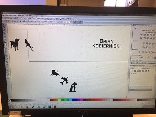
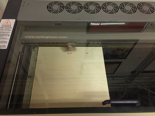
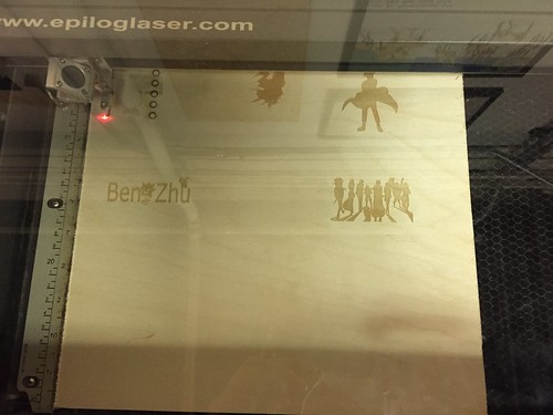
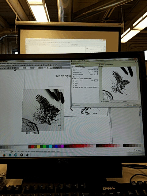
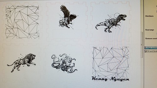
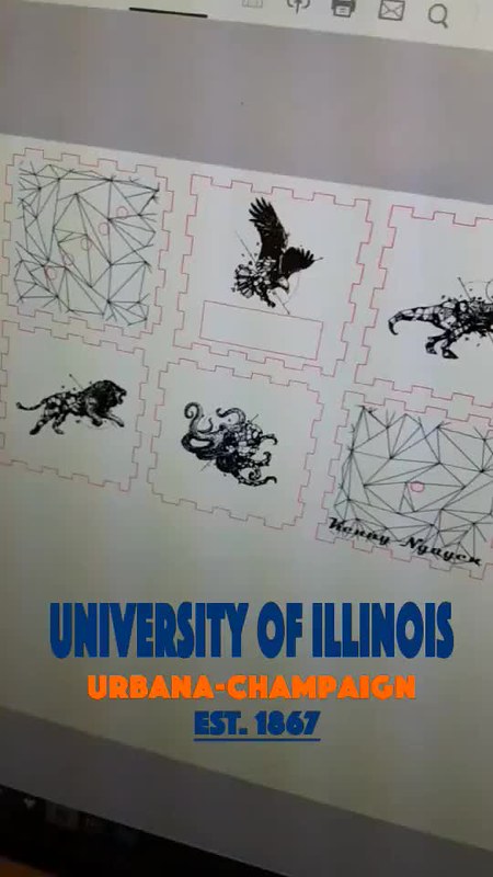
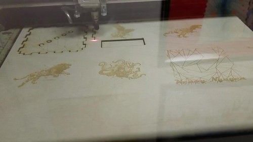
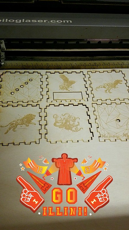
The objective of this week was to make the wood box that would house our blinker box. Helping our group along the way were Alexis Papak and Clinton Gandy. Alexis and Clinton gave us a great tutorial of Inkscape, the software that we used to design our boxes. Inkscape is a free, open source program that is very easy to use.  We downloaded a template from the Internet for the press-fit box, but we had to make some changes to ensure the laser could cut the wood properly. For the laser to cut through the wood, we had to format the lines to be red and .001mm thickness. Then we learned how to format images correctly. We were able to take silhouettes from Google Image and use Inkscape to trace their paths to ensure only the actual design was engraved. We were allowed to decorate the boxes however we wanted, but I kept mine relatively simple. However, it did spark my interest in little projects I could make myself. Once I finished my design, Alexis double-checked that all the lines and images were within specification and I saved it to take to the laser. Clinton helped load the file onto the computer where we made some final adjustments to the settings and sent it away. The Fab Lab has two lasers, and I used the Universal Laser Systems X-600, which reads PDF files to make the cuts. After resetting the origin and turning on the ventilation to prevent fires, I started the laser and away it went. The laser first etched all the images from the designs, going back and forth like a 3D or traditional Inkjet printer, then made the actual cuts very quickly. Once it was finished I was able to pick it up right away and take my pieces back to my desk.

IMG_1120

This week, I found another Instructables article with tips and tricks of designing for laser engraving.  The post offers some “inside tips” on how to achieve the best outcomes.  Like 3D printing, you have to pay attention to some pretty small details to make sure your design turns out as planned.  I also found this collection of open designs.  While we don’t need any more designs for the blinker boxes, they may be useful for our group projects or even personal uses.

IMG_1123

Because we used a template, the box wasn’t tight enough to press together and hold so I will need to use glue when assembling the box. However, I could still assemble it to see how it will stand together with the LED’s and Arduino inside. For our semester project, my group can make a housing with a press-fit box and engrave designs onto it, or make a storage box to keep it in. I am excited to see how my team would be able to use the laser for our project. Next week we will move onto the coding section and I am exited to get that experience in our final week at the Fab Lab.


Week 7: Arduino and Lights

This week, I got back my laser cut box and I was so excited on how my design came out.
The design that was laser cut.

Furthermore, this week the white group was assigned to the main lab in order to learn how to program an Arduino board. This was my first time actually seeing a computer board up close and I was definitely quite surprised by how it looked. Personally, I thought that it seemed quite fragile and easily breakable. However, it was quite sturdy and it could hold quite a bit of force. Along with the Arduino board, the following things were included: The Arduino packet FabLab provided.

Using the package, we connected power and ground to the board by connecting pins. By doing so it helps “power” and enables the user to correctly use the Arduino board. For example, we connected the pins and linked power and ground together so that later on we could “power” and enable the LED lights to blink and turn on. One of the steps to put together the blinking LED lights.

After assembling all the parts of the hardware, we had to “assemble” the software together and make the LED light blink by coding on the Arduino software. Here is one of the activities that we did:

The Arduino code in which sends a SOS through Morse Code.

This example was coded so that the LED lights would emit a Morse Code for
“SOS.” After coding for the LED lights, we had to add sensors. Personally, the sensor was the hardest part of building the hardware. Because the breadboard was so tiny, it was hard to find empty rows and columns to use for the sensor. However, with some help, I was successfully able to make the LED lights blink when I waved my hand over it. After completing and successfully doing so I felt such a sense of pride because, through my first attempt, I was able to successfully complete such a feat.The completed assembly for the workshop.

This week will be very applicable for our group project. Our group project is going to be a feedback droid in which there will be sensors, so learning how to connect the breadboard to the Arduino board through the pins. The coding as well using the Arduino software was very informative and will help us in the coding for our droid. I am excited to be using such new skills in my future group project. Next week, the white team will be soldering so that the LED lights will fit into the box well.

Soldering at the FabLab

After last weeks lab session where our group wired a breadboard and uploaded our code onto an Arduino Uno, the next step was to set stone our circuit design with the help of a soldering process in which wires are joint together by melting metal. Our task was to wire up the LED’s and the photoresistor so that they have fixed joints and can be easily wired into the arduino board. As we sat around the table with soldering machines and wires in front of us, we were pretty overwhelmed and somewhat scared about using the solder as even a small touch of it onto our skin could result in a 2nd degree burn. Some of us used “soldering helping hands” helpers to keep our wires fixed in place while soldering them together as shown in the picture below. Due to the delicate nature of the soldering components and wires the helping hands proved to be very useful in keeping everything stationary and out of harms way.

Soldering basically uses a hot iron rod and a solder flux (a metal with a low melting temperature) to join two wires or two metal components together. The hot iron melts the flux in between the junction of the two metal components and quickly solidifies thus keeping them in a fixed state. Due to the fluxes metal characteristics it does not impede the flow of current in the circuit. The instructor was incredibly patient and helpful as she guided as through each of the soldering tasks. I quickly realized that soldering was an art form of its own as it required immense precision and concentration. The worst part about the soldering process is the smoke which is given off when the flux melts and it can be really suffocating at times. Due to this we took a 15 minute break to clear the smoke and also to rest our eyes.

Finally after soldering and wiring the arduino to our LED’s we powered it up using a battery and yes it did light up! In the video here, you can see the LED’s light up when my hand is close to the photoresistor and vice versa. The next step of the project is to laser cut a wooden box to house all these cool LED’s.

**Here is a link for beginners to learn more about the soldering technique!

Arduino Testing and Experience

This was week two in the Fab Lab. My group, group White, was switching from laser cutting to coding and testing Ardiunos. I have had very little experience with coding and zero experience with Arduinos. I was not sure how this would go.

The first thing we did was grab the box we had laser cut the week before along with the pouch that would help us assemble our Arduinos. Each of us sat at a station with two monitors. On one monitor we pulled up a slide show that would help us follow along with how to code. We ran a series of tests to make sure our Arduino would function properly. I found the most difficult part of this process was figuring out where exactly to place everything on the bread board in order for it to work. Luckily the final product turned out!!

When I looked more into what kinds of things arduinos are used for, so many things came up! Something that stood out to me was a “smart house” controlled by arduinos. At first, my mind immediately went to the Disney movie “Smart House” that was created in the late 90s. When I read into it, I found out that arduinos control more of the environment of the house. For example, controlling the internal temperature of the house, letting know which windows are open or closed, or which doors are locked. These are small things, but they are helpful. Every time my family and I leave our house, we ask the same questions. We are not for sure we locked all the doors, turned off all the lights, or even made sure the stove was off. An arduino for our house would be very convenient. We would not have to wonder and would have the answer at our fingertips by checking our phones. Click here to read more about smart houses.

I am curious to see what arduinos hold for the future. I know I have only recently had experience with probably one of simplest functions of an arduino, I was amazed. I have never made something that was motion sensitive. I think exposure to arduinos will broaden our ideas as a class for our development of our products for Digital Making. This could make something touch sensitive or notify you what the temperature is. Arduinos can upgrade an idea that you may of already had!

Week 7: 2nd Week at the Fab Lab (Laser Cutting)

Aside

For our second visit to the Fab Lab, each group switched stations to work on a different portion of our final project. This week, I attended the Laser Cutting session. Though the workshop is somewhat secluded towards the back of the Fab Lab, it certainly shines through as one of the more unique creative processes the Fab Lab has to offer (no pun intended).

In my last workshop, we focused on designing the physical circuit for our light-sensitive boxes. This week, we continued with moe hands-on work dedicated to making the appearance of the project aesthetic and to our liking. By using specifically designed software, we were able to create layouts for our boxes that we could customize. We first gained the template after entering our desired dimensions into an online resource, and then imported that file onto the lab computer software Inkscape to customize them. We were able to select images online to use as stencils for the panels. The images had to be completely black & white, as well as properly pixelated. The laser cutters are incredibly precise, and are able to stencil out wood portions with cuts of down to .001 m in width, resulting in flawlessly fitting pieces and stellar quality of silhouettes. One of the most amazing bits of all this, is that each person’s cuts only took approximately 20 minutes maximum, way faster than a conventional 3D printer. While it is certainly a sight to see something create out of nothing, some don’t realize that you can also achieve great designs by taking away from what you already have.

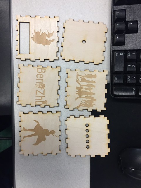
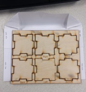
Smaller scale sample box pieces
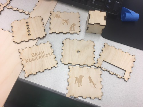
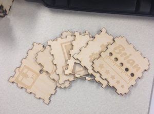
For my custom designs, I chose each side to represent a field of engineering/design as I am an engineering major. Four sides included images reminiscent of electrical, mechanical, and computer engineering, as well as architecture. The underside of the box features a 3D printer silhouette as well as that of a laser cutter, the two main methods of design that my group will probably use in our final project. The remaining side just has my name with a special measurement system composed of a ruler image and different sized stars to represent the brightness of the LEDs.

My pieces

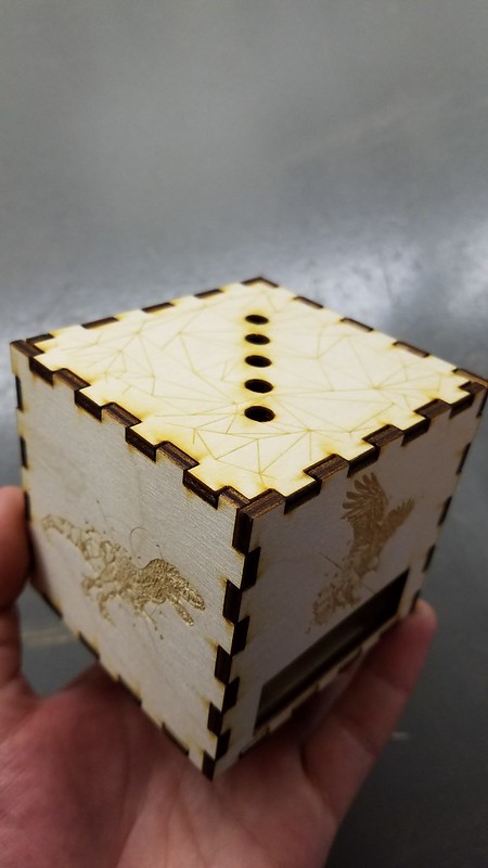
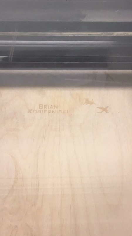
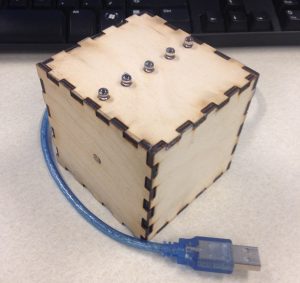
Sneak peek of the completed project

Now that I’ve completed both the physical portions of the workshop, I’m excited to take part in the coding session next week, where we will program the Arduino with the desired code to allow it to respond as we want it to. I’ve thoroughly enjoyed these Fab Lab sessions not only because we get to create a custom project for ourselves to keep in the end, but we also get to see multiple types of engineering and designing intertwined (specifically electronics, mechanics, and programming) into a single project. It’s been a fantastic experience to work with all these different processes, and I’m hoping that we can incorporate every one of them into our final project.

Laser Cutting

After soldering Arduino circuit last week, we came to the Fablab the second time this week for the next stage of our project. Arduino circuit is an internal function unit of our project and we successfully made it last week. This week, our goal was to design an exterior shell for the project. First thing first, we needed to design the patterns or pictures with the help of the open-source software Inkscape. Inkscape was quite user-friendly and we were able to use the basic functionalities to design our own work after listening the short demonstration shown by the instructors at the FabLab. Basically, we would import our favorable pictures from the Internet to Inkscape and then trace the picture so that the picture would have been transformed into the vectors. The transformed pictures could allow the users to precisely adjust the pictures points by points.

IMG_3796

The container consisted of 6 pieces of wooden board. Thus, we designed the size and shape of each wooden board on Internet. After importing the board outline into the Inkscape, we would place our customized imagines into each board. By default, we set color in RBG mode with 255 for Red and 0.001 m for the size of cut. We had to ensure that these parameters were definitely correct so that the laser cutter could precisely conduct the objects we designed. As you can tell from the picture below, I am a big fan of comic. The images I chose were Batman, Naruto, Pokemon, and Onepiece.

IMG_3797

Although the laser printer was efficient at producing customized artwork, we only had two laser printers while 8 objects needed to be printed. Thus, I waited for almost 15 minutes before the printer started to print my own object. I was so excited when seeing my design printed into physical objects. Now, I had the internal circuits and external containers. Next Monday, I would learn how to code and import a program into the circuits. I can’t wait to see my final project when I finished all of the three different but inter-related parts.

IMG_3798

Arduino Light Box With Ultrasonic

This week was the second part of our session with FabLab and I was so eager to learn more about what we would place inside the boxes we had laser printed last week. I got to work with Brandon Rice (Lab Assistant and Consultant) and Aakanksha Ardhapurkar (Lab Assistant) who taught us how to make LEDS controlled by an ultrasonic sensor. Honestly, going in to the session I was nervous because I had no experience with hardware though I did have some in software. Many of my friends had talked about using Arduinos as a great prototyping platform so I was excited to play with both hardware and software through it.

In the lesson we started out with learning how to make blinking lights on the hardware through a code that we would apply. In setting up the hardware we used an Arduino Uno, cable, LED, jumper wire, breadboard and resistors. I thought it was so amazing how there were so many different numbered and powered pins within the board that could create such powerful connections. Because all the objects we used to put on the breadboard and the Arduino was quite small it was sometimes hard to find the exact place to put it and those little mistakes would lead the blinkers to not blink. Brandon had taught us how the circuit would work in regards to the arduino, breadboard and LED as electricity only flowed in one direction around a circuit we had to put them in correctly. Once we finished building our hardware we started working on the software through Arduino Software that was in an integrated Development Environment, the software could be used to write code and upload codes to the Arduino board. There were various settings that we could change with the lights but we were specifically working on making them blink and the settings can be seen on the software (File à Examples à 01 Basics). Once we connected the software to the Arduino board we would upload it, though some of our boards took awhile to function properly we all learned that many of them were little issues with the wires that we hadn’t put in correctly. What I found great about this project was that even though we would make mistakes we had the chance to fix them and still make the system work properly. We were given some other activities such as hacking the code and making the lights blink in a certain beat. Near the last part of class we had complete the ultrasonic sensor wiring diagram and as a group we definitely worked together to make it all happen and all our boards ended up accomplishing what we had hoped for with the sensor lights.

Though we had to tear apart the hardware, I can’t wait for the soldering process when we put everything together. So far I feel that I’ve been learning so much from my experience with the FabLab and am very grateful!

In the process of building:

Final results:

Fusing Our Business and Making Aspirations

In the ongoing three-part series at the Champaign-Urbana Community Fab Lab, our class this week primarily focused on the process of soldering, yet another making activity that I was previously unfamiliar with. While the instructional course ultimately proved to be very time consuming and required incredible delicacy, there is little doubt in my mind that this is a crucial tool in any maker’s arsenal of building tools. Soldering allows for more accurate and uncluttered connections between various electronic parts, such as wires, resistors, and other components. An additional benefit of soldering is the ability to maintain the original shape of the soldered metals, considering that the solder has a much lower melting point than the adjoining metal. Since the fusing occurs at much lower temperatures (albeit still incredibly hot), the metals that are being connected do not warp in shape or size, nor do they melt. Lastly, soldering allows for the joining of multiple wires using a single focal point. This can allow electricity to be conducted, as all the wires have been bonded together.

To begin, we were each given a simple kit consisting of numerous wires, six resistors, six LED lights, a lead coil and a photoresistor. Our group leader then demonstrated the actual process of soldering: the heated iron was applied to two overlapping wires, and, when hot enough, the lead coil was briefly touched to the juncture. The heat would melt the lead and fill the joint, essentially bonding the two wires together. We were also shown how to use two different “tricks of the trade”, one being a device fondly called the “helping hands” (pictured in the above photo), the other being double-sided scotch tape. When using the helping hands, one wire would be secured by one of the claws, while the other wire was placed in the other claw. Once the claws were positioned so that the wires were aligned, the process of soldering was made exponentially easier, as the claws were able to maintain a steady hold of the wires. The duct tape worked in a similar fashion, perhaps with less precision. I personally favored the helping hands device, as the setup time was minimal and it allowed for the soldering of more complex joints.

After soldering each wire to a resistor and subsequently each resistor to a LED light, we then connected certain wires to the Arduino board. This effectively produced the same light dependent resistor that we created last week, however the resulting product had a much different appearance. The soldered wires gave the resistor a much more streamlined, uncluttered look, one that made it significantly easier to track and identify connections.

While at first the process seemed laborious and too precise, I quickly learned the added benefits of utilizing a process like soldering. The resulting product boasts useful and concise connections while maintaining its shape and size. Going forward, I hope to incorporate soldering in some capacity into our final project.

Coding with Bread(boards)

This past week our class was once again at the Fab Lab where we were able to learn how to code with Arduino breadboards! Here we utilized cables, a breadboard, Arduino, and a couple of LEDs. We learned the basics of coding with Arduinos in order to light up a single LED first. Along with that, we learned how ECE works in order to wire up the breadboard. Although we only really touched the surface of ECE it was pretty cool to learn how another discipline works outside of the College of Business. The very first task was to try to figure out how to light the LED and make it blink with the SOS pattern. Which could be done by figuring out the right amount of timing to delay the lights within the code so that it would blink in the right pattern.

Following that more complexity was added to how the lights would blink. We added more lights to the board so more light was blinking and changed up the code. How the relationship between the code and the Arduino worked was that we would change the configuration on the breadboard, hook it up to the Arduino, then upload the code from the computer into the Arduino. After everything was uploaded you would sit there and wait to see if everything worked ok and if it did the LEDs would start blinking!

It was really cool to be able to build something totally different than what we would make at the MakerLab. For the final step, we added a sensor that would make the lights blink depending on how much light was available. If a lot of light was available then the far right LED would be lit then it would descend to the left as light availability lessens. Finally, if there was no light available then the whole thing would just start blinking.

Animated GIF  - Find & Share on GIPHY

The end result was very cool and I was amazed that I was able to build something like that in such a short amount of time. Albeit we had a lot of help from our amazing instructors. A lot of the breadboard configuration and the code was premade but it certainly got me a lot more interested in coding Arduinos. The final step it seems to be for the whole project is to put that blinking breadboard inside of our wooden cube – needless to say I’m pretty excited!

IMG_0499

Inkscape and Laser Cutting

The second session at the FabLab this week meant that we were at a new stage for our light receptor boxes. Last week we had the pleasure of soldering the circuits together and testing it on the Arduino units. This week our group went to the laser cutter to create the box in which our project will be encapsulated in. We utilized a free software called Inkscape which is similar to Adobe Illustrator but I found it a little easier to use. We started off by learning the basics of taking an image from the internet and then vectoring it to be able to get the black lines out through the Image Trace option and that allowed us to make basic images into vectors that we can work natively on the software.

20170306_151900

This made it very intuitive to be able to take any image with defined black and white borders and make it into a vector so we are easily able to manipulate the points and add or subtract portions of the image. We obtained the box layout from a website that the FabLab provided us and then added our own designs. This was the outcome of me scouring the internet for my favorite graphic designer from the Philippines, Kerby Rosanes.

20170306_153427

Upon finishing the files and layout, you transferred the document as a PDF file to the printer and I was using the EpiLogue printer which is a very strong one that can cut a variety of materials as well as thicknesses. You had to make sure that the colors and sizes of the cuts were 0.001 in and that the color was in RGB mode with 255 for Red and 0 for everything else. The raster aka engraving could be black and any size. The laser cutter was very precarious and we had to make sure that the settings were 100% accurate.

Snapchat-1358921269

Here you can see a time lapse I had made through the rastering process.

20170306_155258

It was very rewarding to be able to see something you design on a computer come to life in a matter of minutes. There was something satisfying from watching it go back and for until your vision comes true. After the printer is able to raster everything, it begins the cutting process which I also speed up the cutting time.

20170306_160446

Here you can see the final cuts and it is all done for me to assemble.

Snapchat-96312379

The picture below shows me assembling the box without the electronic components in it yet and so I thought it looked very cool and can not wait to combine everything together next week after we learn to code the Arduino.

20170306_161242

A helpful article I found while using the laser printer was found on Instructables with 10 helpful tips and tricks. Going forward I am excited to be able to use the laser cutter for our final project as it is less intimating as I thought it was. I will also probably use this tool for other projects too since it is fairly easy being able to use this tool.