I can’t believe that it is so close to the end of the semester now! BADM 395 Digital Making is such an interesting and explorative course that I learnt so much from it. I used a lot of skills I studied at the first half of the semester for my final project and I believe that I will benefit more from the skills in the future.
Skills:
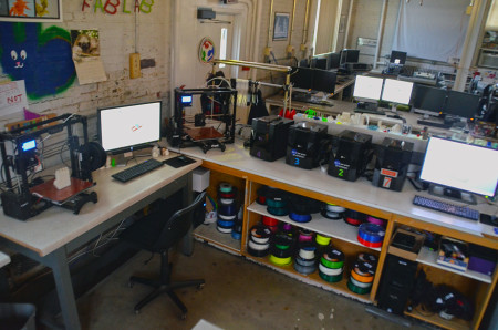
3D printing
Here, I want to not only talk about how I study the 3D printing technique, but also emphasize the idea behind the 3D printing. At the second class of the semester, the director of CUC Fablab, Jeff Ginger, said, “Instead of doing it yourself(DIY), we need to do it with others(DIWO)”. I think 3D printing catch the essence of the Internet and leverage the synergy among different designers. The first 3D printing object I chose was a batman model. The model was quite complicated and would take 10 hours to print, so I had to print partly for the sake of time.
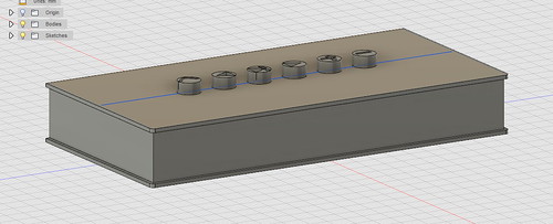
Fusion 360
Fusion 360 is one of the most user-friendly design software I have ever used. Fusion360 is a computer-aided design application for creating 3D digital prototypes. Similar to Cura, Fusion360 enables users to design prototypes or edit other’s projects. Under the guidance of Jeff Smith, an industrial designer at Autodesk, I quickly learnt how to create simple 2D patterns such as line, curve, square, and circle. Then, I knew how to use the more advanced tools to create symmetric objects. I designed a speaker by using Fusion 360.
Design with Empathy
This is not a certain skill I could use directly but it is much more meaningful for each designer than the 3D printing or the skill to use Fusion 360. Design with empathy focuses on the importance to resonate or experience others as if from within their own skin so that we could have a broad perspective about the whole issue. Then, we could generate proposals that cater to different stakeholders.
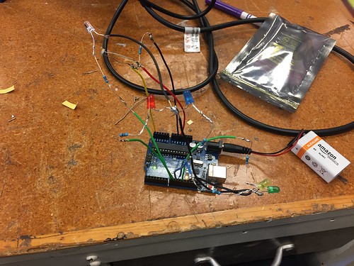
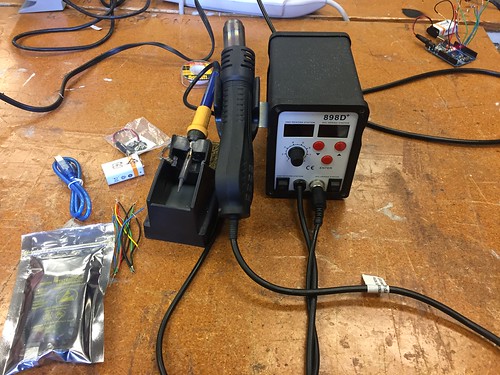
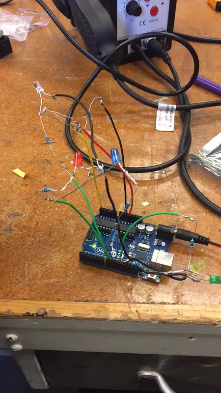
Circuit Board Design
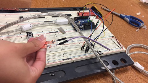
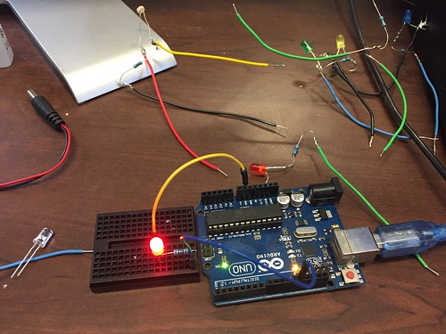
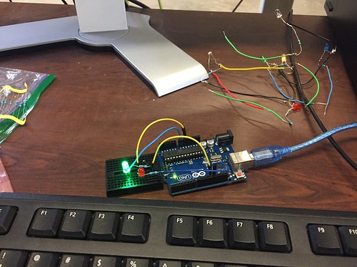
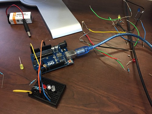
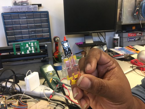
Circuit board design allows me to create something more interesting and interactive with the 3D printing. The first study session of circuit board design is pure electric-related. I need to make a system that can automatically turn on the LED lights when the light sensor can’t detect light. The main challenge I met was to solder 3 wires together without the help of the holding tool. As you can see from the video below, the system works properly as demanded:
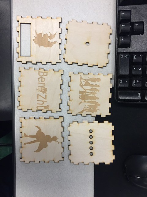
Laser Cutting
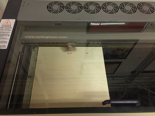
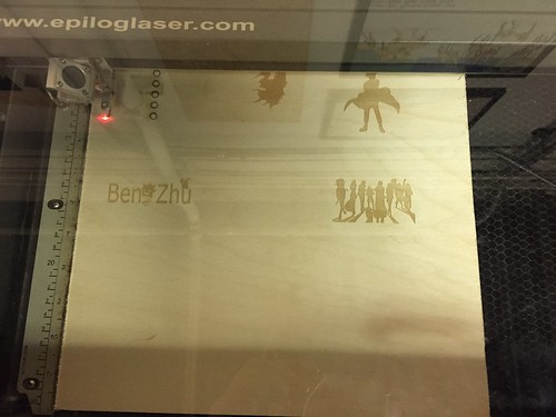
Laser cutting is another important and useful skills. I learnt how to use Inkscape to design the patterns or pictures first. Then, we divided the wooden board into 6 different pieces. Because I am a big fan of comic, I chose Batman, Naruto, Pokemon and Onepiece for the cutting.
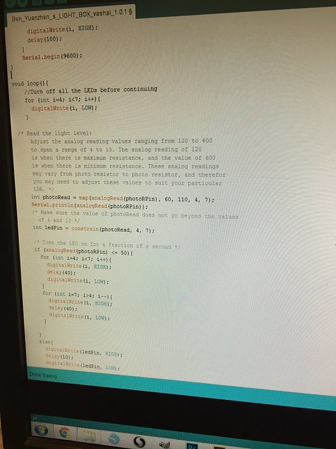
Coding
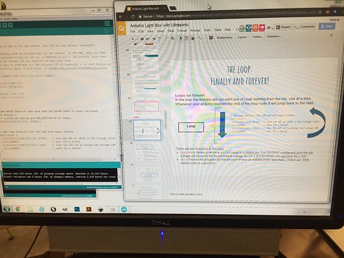
Coding is the key to control the circuit/ Arduino. At first, we learnt how to control one single LED light on/ off. Then, we were required to use the single LED light to send SOS signal. The second challenge was to make two LED lights flash alternatively. The last problem was to integrate the photo sensor into the circuit and use the sensor to control the LED lights. By solving all these problems, I studied the syntax and logic to code. More importantly, I knew how to ask the Arduino to do the things I mean.
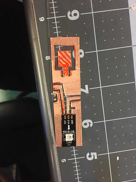
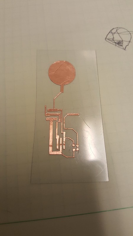
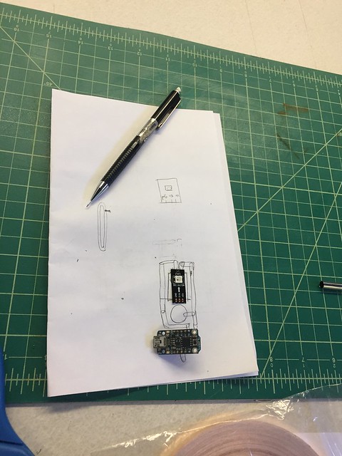
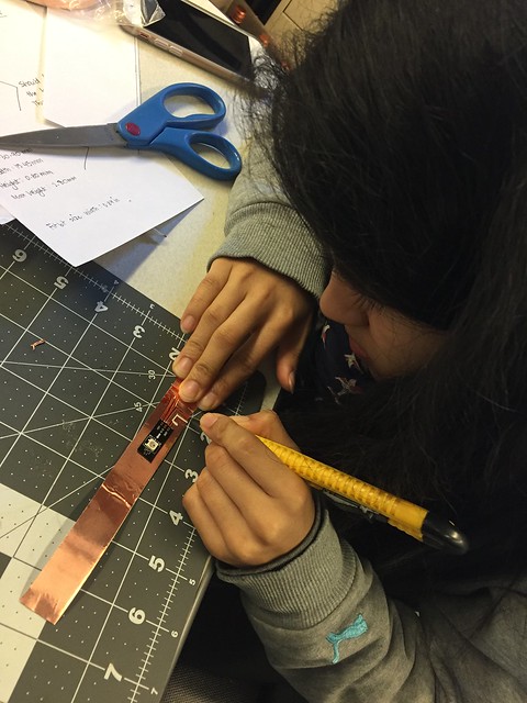
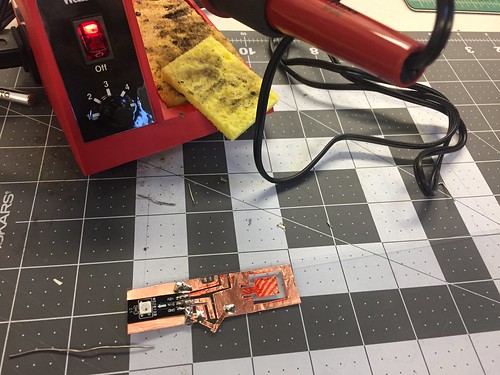
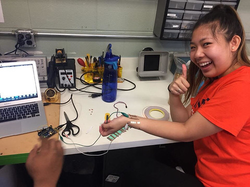
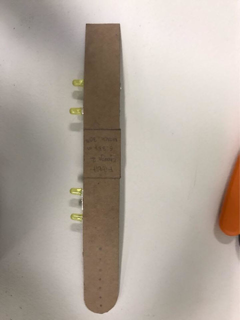
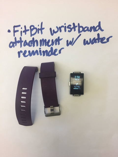
Project/ H2GO
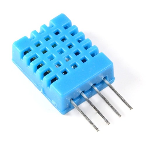
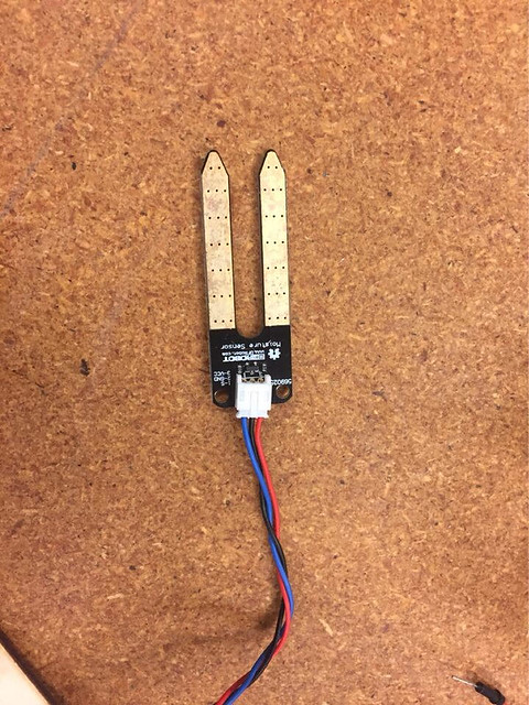
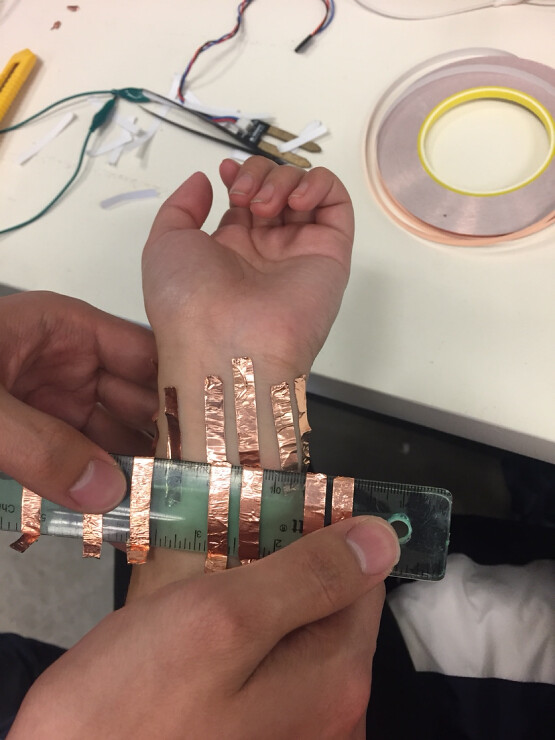
The capstone project we did was a dehydration band. Basically, the band could measure the hydration level of the users and flash lights to remind users to drink water. The band consisted of two parts, the frame and the Arduino controller. We used the 3D printer with the semi-flex material to make the frame. To minimize the size, we made the humidity sensor by ourselves and integrated the sensor with the Arduino controller. Below are the pictures of our deliverable:
Summary
I can’t say that I will use 3D printer a lot or I will be a designer in the future, but the experience of learning all the knowledge helps me to realize that I could do much more than I expected from myself. The idea of design with empathy will be useful to me no matter what kind of job I will do. I need to consider the actual demand from the perspective of the users. Meanwhile, I also see how amazing the teamwork could be in the final project. By sharing the different skill-set, we as a team turned in a wearable that I could never make by myself alone. I feel so lucky that I chose to take this course at the end of last semester.