Takeaways from a Semester of Making

This semester I had the privilege of absorbing all that the Digital Making Seminar had to offer. Whether it was working with laser cutters in the Fab Lab or tinkering with Fusion 360 in the Armory, this class gave me unprecedented exposure to the making process.

Expectations Before the Course

Heading into this semester, I was under the impression that the content of this course would strictly deal with 3D printing and the technology associated with it. In that regard, our class had countless opportunities to explore Cura, TinkerCAD, and Fusion 360, among a few others. What I was not expecting – and something that I was pleasantly surprised about – was that we also gained insight into numerous making techniques. In other words, while I believed the class was going to delve a deep into one certain aspect of the Making Revolution, in reality it actually spanned a multitude of types, and some that I had never even heard of prior to the course.

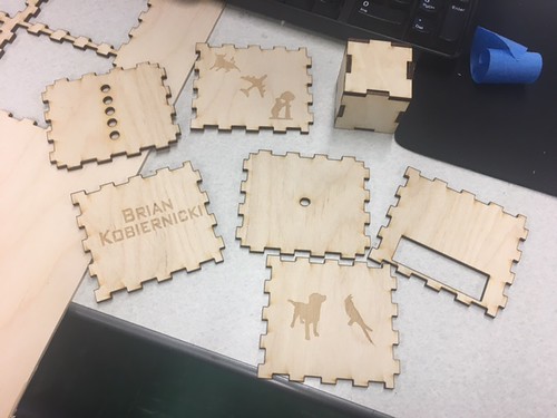
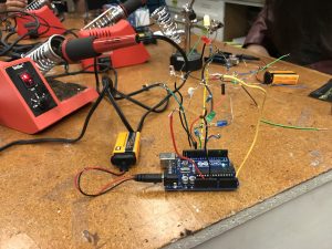
I believe that I, as well as the rest of the class, benefitted more from this sort of kitchen sink approach since every week we were constantly learning something new and different from the week prior. Relating this observation to our final semester projects, having the ability to draw from a wide spectrum of making techniques allowed each group to develop incredibly unique products. Some groups utilized the programming aspects (such as with Arduino Unos and Raspberry Pis) while others incorporated the more manual techniques we learned, like laser cutting and soldering wires. Through this process, I learned that I greatly enjoy the constant learning. Also crucial to my enjoyment of the class was the fact that it was composed of not just College of Business students, but rather a conglomeration of engineering majors, art and design majors, business majors, and entrepreneurs in general. For me, I found this to be very beneficial. While the majority of times I struggled in the ideation part of the process in terms of devising practical and applicable products, students with more creative minds were able to fill the knowledge void. Similarly, if at times I struggled with certain technologies, the majority of the engineering majors in the class had previous coding, programming, or making experience and were more than willing in helping me to succeed.

3 Main Takeaways

1)The Maker Movement is for Real

Before beginning this class I had an inaccurate understanding of the Maker Movement. I thought it was still in its infancy, and I had no idea it was on the immense scale that it currently is. The applications it has on modern society are truly incredible, and I look forward to following its growth over the long-term future.

2) 3D Scanning and Printing

3D Printing has exploded and an exponential rate, and the possibilities it has, from at-home printing to construction, are limited only by one’s imagination. For example, just over the duration of this semester, 3D printing has been used to build homes in Russia, as well as the building turbines for GE. In the case of the house in Russia, it was 3D printed in under 24 hours, at a cost of only $10,000. Although some houses have had 3D printed parts printed remotely and then brought to the construction site, this house was built completely on-site, using a mobile printer. The GE turbine, on the other hand, is able to withstand higher temperatures and pressure than current market offerings. These are just two examples of the immense potential that 3D printing presents.

3) An Introduction to the Design Process

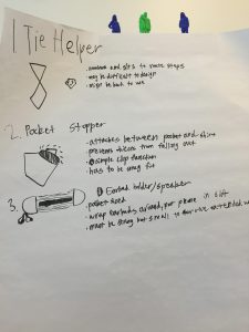
This semester definitely opened my eyes to the design process. From the ideating stage to rapid prototyping to receiving user feedback, our team learned a great deal about how to design a product, from beginning to end. I personally found the ideation stage to be the most difficult, as I struggled to devise creative yet applicable and practical solutions to everyday problems that we encounter. Overall, this class was a great introduction to the skills and technology used by makers around the world, and I look forward to cultivating this interest after college.


3D Scanning and Project Progression

This week we returned to the MakerLab after a three-part tutorial series at the Champaign-Urbana Fab Lab. Before continuing work on our final semester projects, Arielle stopped by again and instructed us on how to effectively utilize a 3D scanner. This technology, she explained, helped her tremendously with making changes to the wheelchair glove that she has been making. Essentially, 3D scanners utilize lasers to scan every part of an object, which is then overlayed together by scanning software to create a 3D model. One software that was spotlighted during the workshop was yet another Autodesk product called Meshmixer, a relatively easy-to-use scanning software that allows the user to edit the scanned model before exporting the file to be 3D printed or added to other parts. Common types of editing include smoothing out certain areas of the model, extruding sides, or cropping unnecessary parts of the scan.

Arielle explaining one of the intricacies of Meshmixer as it pertains to her product:

After her presentation, we were allowed to try our own hand at 3D scanning using a mobile scanner. While Arielle made the process look painless, we quickly encountered a variety of challenges when attempting to scan our objects (our own heads). Firstly, the scanner struggled to pick up certain complex features of the face, such as specific details of the eyes and ears. Next, the scanner required very strong lighting, as the lasers it employed required light to bounce off the object, similar to a camera. This led to another hurdle; any users wearing dark clothing, such as a black jacket or shirt, struggled to obtain an accurate scan below their neckline. As with many obstacles faced throughout the course, over time and with much practice we were able to overcome these complications. Once scanned, we first cropped unnecessary features from the scan and solidified aspects of the object that were not properly scanned. From there, we imported the solidified 3D model busts into Cura to finalize before being printed.

An example of Peter’s bust after being exported into Cura:

For reference, here’s a simple and quick tutorial on Autodesk’s Meshmixer:

After taking a shot at 3D scanning, we returned to focus on our group projects. Our group, Team MakerLax, was able to create the initial model of our product using both Autodesk’s Fusion 360 and TinkerCAD. This first prototype certainly leaves much to be desired as there are a variety of adjustments to be made, however I am glad we were able to design a preliminary model. This way, we understand the direction that we are headed in and can add or subtract features accordingly. I look forward to adding a few more features to the product this upcoming week.

The initial prototype of our “Tie Helper”:

Kickstarting the Prototyping Process

This class session focused on finalizing our project ideas and delving into the rapid prototyping phase of the project.

Ultimately, after weighing a handful of options, Team MakerLax chose to begin creating a prototype for a tie knot helper. Essentially, what this product does is allow users to tie a tie on-the-go, with little hassle. We believe this idea is useful for four main reasons. It is narrow in scope, with the tie helper serving a singular purpose and not attempting to accomplish a variety of tasks. It is relevant to our current environment, as the majority of college freshmen that we have surveyed have little-to-no knowledge on the intricacies of tie knots. It is convenient, with the ability to be used in virtually any environment. Finally, it is feasible and holds a competitive advantage over utilizing other forms of education, such as YouTube videos. While how-to videos are effective in some cases, they do not offer the physical presence offered by our product, nor can they be used while running to an interview.

Above are the two initial designs we created, both composed of cardboard. While the one on the right offers more guidance, the one on the left can be easier to detach once the knot has been tied. One of the primary challenges associated with a product like this is being able to reuse the template, which requires the user to have the ability to remove the product once the tie has been finished. In order to do this, our next step is to prototype a metal using a flexible plastic filament, that can be bent or maneuvered in such a way as to be removed as the final step. The other idea we developed was to give the product the ability to be folded into smaller pieces, similar to many of the designs we have seen in the MakerLab. This would require more advanced engineering and design of the product within Fusion360, however we believe that it will ultimately benefit the user in the long run, as the template will be able to fold and fit into a suit pocket or a briefcase on the way to a meeting. Next week, we plan on printing a few plastic prototypes that will allow us to determine the true feasibility of the design, as well as potentially offering other ideas to incorporate into the product. Ultimately, we hope to decide on a final design so that we may begin finalizing the project details.

Concluding Our Time at the Fab Lab

This week marked our last class at the Champaign Community Fab Lab, an innovative and dynamic maker space located on the campus of the University of Illinois. While in previous classes we have worked with soldering joints, encoding Arduino Uno circuit boards using Arduino’s open-sourced software, and wiring resistors and LED lights into breadboards, this week was the culmination of all our of efforts. We were able to finally assemble the photo resistor in its entirety. While in the past two weeks we took care of the actual photo resistor and its assembly, we still needed to create a structure that would house the part. In order to do this, Clinton and Julia, our two exponentially patient teachers, instructed us on the basics of Inkscape (a graphics editor similar to Adobe Photoshop), and on using the two laser cutters housed at the Fab Lab. The objective of utilizing these tools was to assemble a wooden, six-piece cube that would house the photo dependent LED light resistor. As mentioned, the software used to create the designs on the sides of the cubes was Inkscape, a completely free, open-source platform that appears to be user-friendly yet still able to make complex designs. Once the template for the wooden cube was downloaded, some manipulation was required in order to guarantee the fitting of the wood. In order for the laser to properly cut the wood, certain formatting and thickness adjustments had to be made. Using Inkscape, we traced black and white images taken from online, and, once finished, the PDF file was loaded onto the laser cutter. The laser etched the designs into the wood which created the downloaded images in a process called raster scanning, while also making the actual cuts to create the box (called vector scanning). The cutting process lasted just a few minutes, as subtractive manufacturing such as laser cutting can be considerably faster than additive manufacturing, like 3D printing.

Above is a picture of what the design of my wooden house looked like on Inkscape. While it cannot be discerned through this picture, there are very thin red lines outlining six intricate boxes. The red lines indicated to the laser cutter what needed to be vector scanned, while the black indicated a raster scan. Below is an illustration of the actual laser cutting process, during which the box outlines were being cut. The whole process, including both the design creations and actual cutting, lasted less than seven minutes, a stark contrast from the relatively lengthy time required for 3D printing.

These past three weeks have exposed to me all that the making world has to offer. While I originally assumed the making revolution focused squarely on 3D printing and additive manufacturing as a whole, this experience has brought about the realization that it is obviously much, much more than that. Going forward, I am excited to see how groups choose to incorporate what we have learned into their final projects.

Week 6 Summary: An Exploration of the Fab Lab Opportunities

This week we engaged in the second phase of a continuous three-part series meant to offer exposure to the myriad of activities offered at the Champaign-Urbana Community Fab Lab. The Fab Lab, although the majority of the class was unaware of its existence prior to this semester, is a leading-edge open and collaborative workspace for design, creation, and printing through the use of computer-driven technologies, such as 3D printing, lasering, inkscape, and soldering. Below is a picture of one of the spaces within the workshop.

One of my favorite aspects of the Fab Lab is its openness to the entire community, irrespective of whether the makers are students or local community members. Everyone is welcome and simultaneously given the resources to collaborate, share, and implement their ideas. Since the making space offers such a vast array of opportunities to its various users, the class was divided into three separate groups during our first session, with each group rotating between the three main functions of the lab: laser cutting, soldering, and coding.

In Brian’s most recent post, he examines the laser cutting portion of the project. The objective of this part was to assemble the wood cube that would house the photo dependent LED light resistor. The software used to create the designs on the sides of the cubes was Inkscape, a completely free, open-source platform that appears to be user-friendly yet still able to make complex designs. Once the template for the wooden cube was downloaded, he initially needed to consider some alterations to guarantee the fitting of the wood. In order for the laser to properly cut the wood, certain formatting and thickness adjustments had to be made. Using Inkscape, Brian and the other members of his group traced images taken from online, and, once finished, the PDF file was loaded onto the laser cutter. The laser etched the designs into the wood which created the downloaded images, while also making the actual cuts to create the box. The cutting process lasted just a few minutes, as subtractive manufacturing such as laser cutting can be considerably faster than additive manufacturing, like 3D printing. Brian’s finsihed creation can be seen below.

Carter’s weekly reflection focused on the soldering aspect of the project. While the initial instruction appeared to be very time consuming and required immense precision, concentration, and delicacy, soldering as a tool in the making and design process can be incredibly powerful and handy, as it offers certain advantages to a product that otherwise would not be available. Soldering allows for more accurate and uncluttered connections between various electronic parts, such as wires, resistors, and other components. An additional benefit of soldering is the ability to maintain the original shape of the soldered metals, considering that the solder has a much lower melting point than the adjoining metal. Since the fusing occurs at much lower temperatures (albeit still incredibly hot), the metals that are being connected do not warp in shape or size, nor do they melt. Lastly, soldering allows for the joining of multiple wires using a single focal point. This can allow electricity to be conducted, as all the wires have been bonded together. Below is a picture of Carter’s finished soldered Arduino circuit board and light dependent resistor.

Charlene’s post focused on the coding of the Arduino Uno circuit board, using Arduino’s open sourced software. Arduino’s simple platform allows for makers with only basic coding experience to still utilize the immense functionality of the technology. Her group was tasked with coding specific behaviors into their widget. In this case, the object that was being encoding was a photo resistor (light dependent resistor) with LEDs. By connecting the LED lights to the light resistor and being guided through some of the basics of the Arduino code, the LED lights extinguished in the presence of light and flashed during times where there was no light (when it was covered by a hand, for example). This first exercise with the Arduino technology was simple enough for us as first-time users to comprehend, yet was still an applicable and useful first attempt at the software, and definitely something that could potentially be incorporated into our end of the semester final projects. Personally, having the ability to view tangible, physical result of our efforts was something that felt gratifying. Charlene’s final product for this phase of the project is pictured below.

While each group has been focusing on a specific activity, we can universally agree that the experiences at the Fab Lab have been invaluable to our making journey. We are constantly attempting to apply what we are learning to not just our semester projects, but also outside of the classroom. I look forward to the rest of our time at the Fab Lab, as well as the rest of the semester!

Fusing Our Business and Making Aspirations

In the ongoing three-part series at the Champaign-Urbana Community Fab Lab, our class this week primarily focused on the process of soldering, yet another making activity that I was previously unfamiliar with. While the instructional course ultimately proved to be very time consuming and required incredible delicacy, there is little doubt in my mind that this is a crucial tool in any maker’s arsenal of building tools. Soldering allows for more accurate and uncluttered connections between various electronic parts, such as wires, resistors, and other components. An additional benefit of soldering is the ability to maintain the original shape of the soldered metals, considering that the solder has a much lower melting point than the adjoining metal. Since the fusing occurs at much lower temperatures (albeit still incredibly hot), the metals that are being connected do not warp in shape or size, nor do they melt. Lastly, soldering allows for the joining of multiple wires using a single focal point. This can allow electricity to be conducted, as all the wires have been bonded together.

To begin, we were each given a simple kit consisting of numerous wires, six resistors, six LED lights, a lead coil and a photoresistor. Our group leader then demonstrated the actual process of soldering: the heated iron was applied to two overlapping wires, and, when hot enough, the lead coil was briefly touched to the juncture. The heat would melt the lead and fill the joint, essentially bonding the two wires together. We were also shown how to use two different “tricks of the trade”, one being a device fondly called the “helping hands” (pictured in the above photo), the other being double-sided scotch tape. When using the helping hands, one wire would be secured by one of the claws, while the other wire was placed in the other claw. Once the claws were positioned so that the wires were aligned, the process of soldering was made exponentially easier, as the claws were able to maintain a steady hold of the wires. The duct tape worked in a similar fashion, perhaps with less precision. I personally favored the helping hands device, as the setup time was minimal and it allowed for the soldering of more complex joints.

After soldering each wire to a resistor and subsequently each resistor to a LED light, we then connected certain wires to the Arduino board. This effectively produced the same light dependent resistor that we created last week, however the resulting product had a much different appearance. The soldered wires gave the resistor a much more streamlined, uncluttered look, one that made it significantly easier to track and identify connections.

While at first the process seemed laborious and too precise, I quickly learned the added benefits of utilizing a process like soldering. The resulting product boasts useful and concise connections while maintaining its shape and size. Going forward, I hope to incorporate soldering in some capacity into our final project.

An Introduction to the Fab Lab

This week we had our first encounter with the opportunities and capabilities of the Champaign-Urbana Community Fab Lab. The Fab Lab, although I was unaware of its existence prior to this semester, is a leading-edge open and collaborative workspace for design, creation, and printing through the use of computer-driven technologies, such as 3D printing, lasering, inkscape, and soldering. Below is a picture of one of the spaces within the workshop.

One of my favorite aspects of the Fab Lab is its openness to the entire community, irrespective of whether the makers are students or local community members. Everyone is welcome, and given the resources, to collaborate, share, and implement their ideas. One maker that we met was trying out a new machine called a “Water Color Bot” (the link to a YouTube explanation can be found here), which uses a specific software to produce complex water color paintings, using precise brush strokes and shading. While he was still becoming acclimated to the software, this is just one example of the various initiatives being worked on in the Fab Lab.

After receiving a tour of the workspaces, we were split into three groups, of which my group was assigned to utilize Arduinos to code behaviors into our widget. Arduino’s are an open-source platform that allows users to code certain behaviors and actions into an electronic object. In this case, our object that we were encoding was a photo resistor (light dependent resistor) with LEDs. Essentially, by wiring the LED lights to the light resistor and writing some basic “for” loops in the Arduino code, the LED lights would illuminate when there was no presence of light (when it was covered by a hand, for example), and would turn off in the presence of other light. I thought it was an incredibly useful and applicable first exercise in Arduino technology. Though the coding and wiring itself were complex, it was simple enough for us as first-time users to comprehend. In addition, I enjoyed being able to see a tangible result of our efforts, as opposed to just writing the code. The final product is pictured below. I look forward to engaging with the lasering/inkscape and soldering workspaces as well, and will definitely look to incorporate this technology into our final semester project.

Identifying Solutions to Everyday Problems

Problem Recognition

Our attention for the week shifted from acclimating ourselves to the design software to analyzing problems encountered in everyday life. In order to do this, we analyzed problems from the perspective of proximity, scope, and practicality. Problems we looked at were local, narrow and specific in scope, and able to be resolved using realistic means. Once we chose our respective issues, we diagnosed responses through the lens of, “How can we…” or “How may we…”. These questions came in the form of improving an already existing product, removing the bad in something, changing the status quo, questioning assumptions, and so forth. After enduring the process, our team came up with three individual problems that we hope to resolve as part of our semester project. The first problem is one that many college students can relate to: struggling to tie a tie. The second also deals with active students, as objects can easily fall out of pants and coat pockets. Finally, our last problem was a lack of portable music optionality. Our ideating poster is shown below.

In addition, Mike Bohlman, the Assistant Dean of Technology at the College of Media, spoke to us about the various maker projects he has embarked on in order to solve everyday problems that he encounters. He touched on three projects in particular: first, there was the airplane radio he designed, then the litter box that notified him when it needed to be cleaned, and finally a smart board game that allowed for reusability while still keeping the consistency in tact. His presentation, along with the two articles “Ten Ways to Evaluate a New Business Idea” and “Creative Sparks”, gave us great inspiration for the rest of the semester, and I look forward to improving on the ideas we have already generated.

Food for Thought

One outside article I found to be particularly interesting was one titled “Dubai: DEWA Innovation Center to Offer Education in 3D Printing & More for the Disabled”, in which a radical initiative by the Dubai government aims to encourage 3D printing. Already, 150 students are enrolled in a program to teach them advanced technologies, such as robotics and 3D printing. This program specifically targets disable students, as learning these technologies, where manual labor is at a minimum, will propel them ahead in the job market.

Another article, titled “3D Food-Printing Developed in Cambridge”, is one that strongly resonated with me. As a self-proclaimed “foodie”, I enjoy food, but not the hassle of going to the grocery store. This Cambridge-based company, Dovetail, developed a 3D printer that utilizes pre-packaged liquids and certain forms of raw ingredients to produce food, and can print food on demand from a smartphone. While I would enjoy this for selfish reasons, scientists also believe it could be one avenue in which to curb the global food problem. Very exciting!


“3D Food-printing Developed in Cambridge.” BBC News. BBC, 13 Feb. 2017. Web. 27 Feb. 2017.

Millsaps, Bridget Butler. “Dubai: DEWA Innovation Center to Offer Education in 3D Printing & More for the Disabled.” 3DPrint.com. N.p., 24 Feb. 2017. Web. 26 Feb. 2017.

An Exercise on Materializing Ideas

The Power of Design Software

Jeff Smith’s presentation on the features of Fusion 360 as a tool to not only visualize products but also as an avenue to create and design new ideas was truly inspiring. As someone who completed all of his college major in industrial design without the use of a computer to now being an expert on all Autodesk products is a testament to the both the continuous growth of the industry as well as the ability to quickly adapt to the revolutionary technology. Besides enlightening us with a rapid and intense beginner’s tutorial on Fusion 360, one of the most innovative features of the software is its “Sculpt” feature, which allows the user to create incredibly complex objects in mere seconds that would otherwise take countless hours using legacy technology. I also enjoyed his spotlight of Autodesk’s revolutionary state-of-the-art initiative in called Pier 9. Located in San Francisco, this workplace is dedicated to exploring and connecting ideas from software to the real physical world, in order to best test, build, and use. In the picture below, Jeff utilized the sculpt feature to create an incredibly complicated yet visually appealing model, which he then rendered and displayed with a full 360-degree panoramic background.


Before class, as a result of watching the Fusion 360 “Absolute Beginners” series of YouTube videos, I was able to make this model.

After class, I was playing around with the software and attempted to create a model of an everyday object that I use quite frequently. Although I struggled mightily at first, take a look at the screenshot below and see if you can determine what object I was attempting to make.

It’s a water bottle! The link to the Fusion 360 file can be found here. The msot difficult part of the design was instructing the software as to what parts were components, bodies, joinings, cuttings, etc. Albeit at first it was frustrating, I gradually began to understand how the software functions.

Biohacking

The second presentation we received was from Dot Silverman, an extremely motivated and ambitious PhD student from the University of Illinois. She introduced us to leading edge enterprises that intertwined the design aspect of 3D printing and additive manufacturing with solving biological and natural problems. She described a variety of projects, however, there were two that particularly stood out. The first was the use of fungi to create bricks for construction. After inserting flour, water, and the fungi into a certain mold, within two weeks the mixture turns into a compound that, once baked, is especially conducive to use as bricks. The other initiative I found to be ground-breaking was the development of soft robotics. As a growing field, soft robotics offers designers and doctors alike a common ground to collaborate and create solutions to some of humanity’s most complex health problems. The article described below gives some insight into this topic.

Food for Thought

This article from WIRED magazine details new developments by researchers who claim to have developed a “robotic sleeve”, which will supposedly assume the functions of pumping blood in the event the patient enters cardiac arrest. Created using silicone as the primary material, this innovative product is a prime example of the literal power soft robotics can have on the healthcare industry. The soft feel of the silicone is less irritating than metal or other materials, which adds to its effectiveness.


References

Further information on Pier 9: click here

Simon, Matt. “The Robots Are Coming for Your Heart.” Wired. Conde Nast, 31 Jan. 2017. Web. 15 Feb. 2017. <https://www.wired.com/2017/01/robots-coming-heart/>.


Pushing the Boundaries of Creative Thought: Design Thinking and Ideating

Design for America’s presentation on design thinking and ideating drastically changed my perception of the product creation process. In accordance with Tim Brown’s article titled “Design Thinking” (https://hbr.org/2008/06/design-thinking), we learned the three steps in the design thinking: inspiration, ideation, and implementation. Many times, it can be easy to perhaps identify a problem that is encountered in everyday life (i.e. the product’s inspiration), however developing an idea to resolve the problem can take a significant amount of effort. The problem itself, in addition, cannot be too broad or impractical. This part of the process is so impactful, Brown believes, that companies are now hiring thinkers to not only implement an idea, but also to originate them.

One particularly interesting exercise the presenter’s guided us through was the design thinking card game. Each team was given three cards: one card had the hypothetical patrons of the product, the other had the purpose of the product, and the third outlined some type of constraint that the creators would encounter. This game definitely forced us to think outside the box, as well as demonstrated from a high-level the thought process that designers experience. In addition, our team used the design thinking process described by the presenters in order to develop our team logo. The logo (which can be found here), incorporated the initials of our last names in an overlapping and visually appealing fashion.

An intriguing real-world example of design thinking that was recently publicized was the German engineering firm Siemens use of 3D printing to create gas turbine blades. The article, which can be found here, details the problem faced by Siemens and their solution. The problem, that the cost to produce these blades were immense and the time needed to produce them was lengthy, was resolved by using metal-based 3D printing. As a result, the time needed to produce this part was shaved from two years to just two months.

Further examples of the impact of design thinking can be found in this article, “3 Great Examples of Design Thinking in Action”, found on the website Medium. One in particular great example of the utilization of design thinking was in creating a foot activated car door, in which ideators realized the challenge of opening a car door when the user’s hands are occupied, such as when they are leaving a grocery store. The foot activated car door allows users to still open the door without needing to free their hands.

In conclusion, I believe that learning about the design thinking process will prove to be crucial as we continue to explore the world of making, and this knowledge will serve as a strong foundation on which we can start to build our own innovative ideas.