One of the best features of consumer 3D printers is their ease of use. All the user needs is to slice their model with their desired settings and upload it to the printer via a USB cable, flash drive, etc. While this is straightforward, there are quite a few intricacies to the process. Slicing a 3D model with “perfect” settings does not necessarily lead to a perfect print. There are a plethora of discerning factors and principles of additive manufacturing that can skew the results. These problems are usually grouped into 3 categories: material issues, software, and hardware. User error can sometimes come into play, but that also usually falls into one of these three mentioned. 3D printing as it is now is not a perfect science, there are many issues prevalent within the technology that prevent it from being greater than what it already is. The slightest mishap during or even before a print begins can cause it to fail or lower in quality. Sometimes, prints even fail for seemingly no reason, and the failed print is simply a one-time occurrence. We can, however, take measures to ensure that we can get the best quality out of our machines as possible. As 3D printing is still rapidly evolving, there really is no “perfect” print. We can get very high quality parts created, but as it stands now there is always something that can be improved in a print. This post is meant to serve as a universal guideline/checklist for getting the best quality prints out of your 3D printer as possible.
1. Filament:
There are a variety of printing materials out there, with the 2 most popular being ABS and PLA. Other types are special exceptions but they usually have the same conditions for printing as one of these two. You should choose what type of filament to use based on what your part requires. Each has its trade-offs.
ABS- Relatively strong with a little bit of flex. Good for parts that will be used a lot, or pieces that you don’t necessarily care how they look. However, it is NOT food-safe, and somewhat difficult to print. It requires a heated printed, and sometimes a little bit of glue on the surface to help with adhesion. It also has a very strong odor so you need a well-ventilated area.
PLA- Probably the most common material used today. It is vegetable-based and is easier to print than ABS. It also tends to look nicer and the prints are more clean coming out. However, it is much more fragile and sensitive to temperature. Therefore, this is good for models that won’t be used heavily and are more for display.
More in-depth info on filaments here: https://pinshape.com/blog/popular-3d-printing-filaments-3d-printer-filament-types/
2. Software
When slicing your file in your slicer, you have a variety of options. Different combinations produces different results, however, these can vary widely depending on the software and the printer, as well as the filament. An important consideration before printing is what kind of software you are using and if it works properly with your printer. Some companies produce their own proprietary software that can only be used with their printers and vie-verse. This makes it easier for users, but in most situations this actually limits the options. They are many other non-locked slicing softwares that can be used with any printer, but not all printers can use any software. Sometimes you will simply have to test these for yourself and see what is compatible with your printer. These are the more common options adjusted by users.
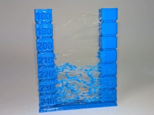
Layer Height- How tall the layers of the filament are in the z-axis(upwards direction). Usually ranges from .1 mm to .4 mm. The finer the layers, the higher quality the print will be.
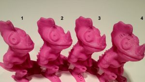 Comparison of 4 different layer heights (finest to roughest from left to right)
Infill- How dense the object printed will be, ranging from completely hollow(0 %) to completely solid (100%). Note that as you get higher and higher in percentages, the difference starts to become less noticeable. The shape of the infill is usually also adjustable, these include hexagonal, rectilinear, or even custom settings.
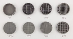 Examples of different infill percentages
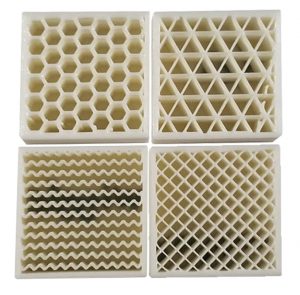 Different infill types
Shells/Perimeter- The number of outer lines the printer will produce on the perimeter of the print. The standard is two. This affects the strength of the print.
Speed- How fast the print nozzle will move during the printing process. Higher speeds give faster prints, but lower quality, while the reverse is for lower speeds.
Supports- If your print has overhangs, depending on the angle, the printer may attempt to build the layers over nothing, causing a drooping effect. To compensate, supports (layers thinner than usual), are created by the printer which can be broken off or in some cases dissolved later. The density of the supports can usually be adjusted as well. Flimsy supports break away easily, but may also be torn away accidentally by the extruder during printing, while more rigid supports are can hold more reliably but are harder to remove.
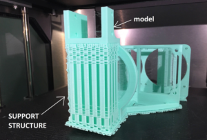 A model with support material
Raft/Skirt/Brim- The more surface contact that your print has, the better it will adhere to the printed during printing. If it has little surface area, there is a possibility that it will actually peel off the printer. In these cases you may want to use a raft, skirt, or brim. There are all similar but each has a specific use. The raft is the most generic and is like support structure but is only composed of a few layers that the model is printed on top of. It is used to provide a larger “footprint” for the model and is removed like support material. Take note however, that the bottom of the print is usually affected by this, as it will tend to be more rough having been printed on top of more material rather than the print bed. A skirt is like and outline of the print made around it. This is to ensure that the filament is flowing properly before the actual print begins. A brim is like a raft, except the bottom layer is printed with the brim instead of on top of it. It provides stability to prints with small contact points, and can be removed or kept on after printing. More info on all of these here https://www.simplify3d.com/support/articles/rafts-skirts-and-brims/
Temperature- Both the temperature of the extruder and the buildplate of the printer can be adjusted in most slicers. The temperature of the extruder and bed should be adjusted depending on the type of filament that you are using. Most filaments come with a suggested nozzle and build plate temperature. Sometimes, the bed may not even need to be heated. Printers also come with fans for the purpose of cooling the components and/or the filament itself. Slowing down or speeding up the fans will affect the flow rate of the filament as well as the quality of the print. This usually doesn’t need to be adjusted but feel free to experiment.
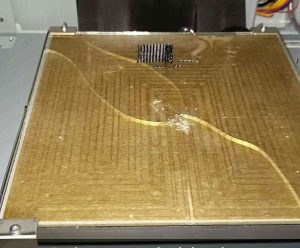
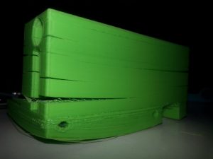 Warped bottom and split layers due to poor adhesion and/or temperature settings
 If you need a heated bed make sure it stays on
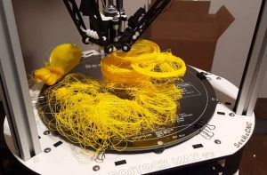
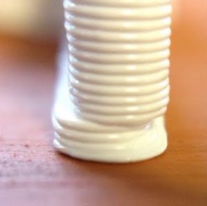
Retraction Rate- Since the filament in the extruder is under constant heat, it will always want to flow out of the extruder. As the nozzle moves about, small bits of filament may be extruded unintentionally. The retraction setting allows the filament to be withdrawn back to prevent this from happening. Too little a retraction rate will cause strings, while too great may actually wind the filament out of the extruder. Once again, a setting that may some testing to find what works best, it also depends on the filament used as well as the temperature.
 An example of too low a retraction rate
There are more settings than those listed, but these are usually the ones that affect print quality the most. Another factor that can affect prints is random bugs in software or issues in the actual model that affect slicing. This is why you should always review your model after it has been sliced in your slicer software before uploading it to the printer. Some slicers have their own file repair settings, but online repair services can be good as well. https://makeprintable.com https://tools3d.azurewebsites.net
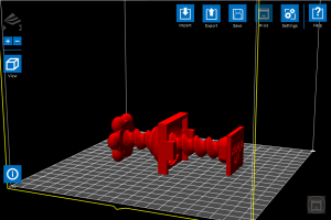 File loaded into software before slicing
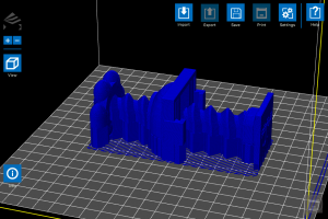 Sliced file output, note the large block in the center of the model that was not present in the original
3. Hardware
3D printers, like all machines, can and will eventually fail and usually require maintenance. You don’t necessarily have to take your printer apart bit by bit, but you definitely need to check on your printer and its components every now and then to ensure every things is fully functional. If desired, you can also upgrade your printer parts with purchasable upgrades, or even print add-ons that will improve print quality.
Extruder- The integral part of the printer responsible for the actual printing. A user needs to make certain that this piece is fully functional and taken care of, otherwise no printing can occur. Taking care of your extruder is relatively simple. Just make sure that it is not overworked and kept clean. Prints that run for hours are fine, but you definitely you should not have your printer running 24/7. After a long print maybe give it a break for a few hours or so. Make sure to exercise proper fan usage. It is wise to have at least one, if not even 2 fans running on the extruder during prints. This improves print quality and extends the lifetime of the component. Also, whenever possible make sure to allow your fan to cool off your extruder instead of just turning the printer off. By allowing the fans to run after a print, the extruder can cool properly and gradually unit the next print. Overheating can cause filament to stop flowing entirely and damage the extruder, so be wary of this. It is also a good idea to maybe open up your extruder whenever you see an issue in printing or just feel like it’s time to clean it. When attempting cleaning, a wire brush is usually the go-to tool as most if not all extruder nozzles are made of metals like brass.
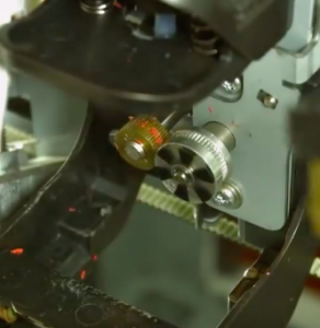 Bits of filament stuck in the drive gears of the extruder can really cause printing problems
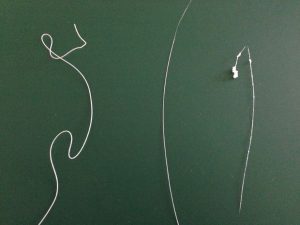 Signs of extruder problems. The left filament strand is fine, while the center is too thin and the rightmost is too “globby”
 A 3D-printed fan mount made by the printer for itself to improve quality
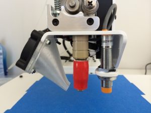
Build plate- Maintaining the integrity of the build platform is key to ensuring good prints. While they can be fixed/replaced like extruders, they are usually much more difficult to do so. One of the most important aspects to look out for is leveling, as in keeping a proper distance between the extruder nozzle and the build surface. Too far and the filament will not stick; too close and the filament will have no room to exit the nozzle and the bed may be damaged. Most printers come with instructions on how to properly level the bed, and some even have auto-leveling settings. Manual offsets can also be input if desired. Like the extruder, it is important to keep the bed clean, as residue from prints and glue for adhesion if used, can buildup overtime and harm the surface as well as your prints. One method of preventing this is using painter’s tape. By applying it over the build plate, you can provide a surface that in some cases is actually better for adhesion than the actual platform, as well as easily peel off the prints afterwards. It also assists in protecting the bed. Many printers also come with beds made from glass, which must be taken care of with caution, as overheating or mishandling of the printer can damage the bed severely and become a safety hazard.
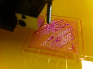 Sign that the bed is adjusted too close to the extruder
 A print with an offset shift due to a loose build plate
 Chipped and cracked glass bed, most likely occurred when trying to remove a print
Motors- In order to drive the axes of the printer’s nozzle and bed, stepper motors are used. One motor is used for each axis(X, Y, and Z), and the extruder and bed can either share all three, or one may posses all of them (in which case that respective part would be the only one moving). These motors are what allow 3D printing to be 3D. Most use tension belts or rods to move the extruder and/or bed. This motors don’t require as much maintenance and checking as the nozzle or bed, but it is certainly a good idea to check on them and perhaps regrease them every now and then. You may also want to check the wiring on the motors, as the repeated motion of moving back and forth can actually break them and sometimes even get caught in the gears, effectively ruining the printer. Unless you’re experienced in electronics, this can be difficult to fix. Taking good care of your motors can not only save you from buying new ones later, but also improve print quality. Everyone can agree that the smoother a print is, the better it looks and the higher quality it is. The accuracy of the prints depend on the stability of the motors. If they are too tight or too loose, your prints will suffer.
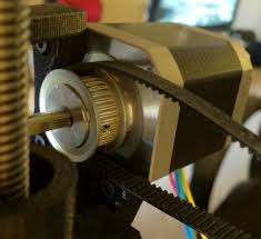 A stepper motor with a loosened belt
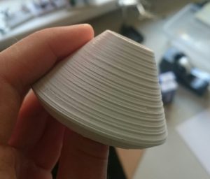 A print with ridging along the z-axis, a sign of wobbling motors


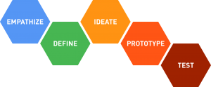 The Design Thinking Process
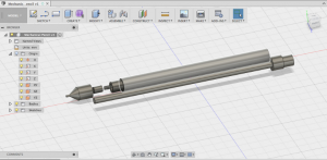 Breakdown of a mechanical pencil
 Circuits
 Laser Cutting
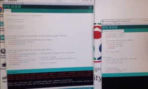 Arduino IDE
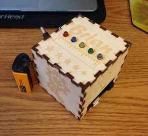 The result of all three
 Scanning
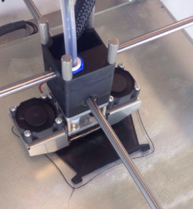 Version of our design printing in black semi-flex filament
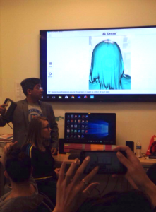 Scanning demonstration
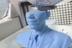 Example of a bust during printing
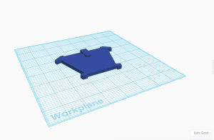 1st edition prototype model of our “Tie Helper” in TinkerCAD
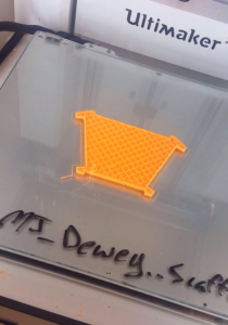 What the printed managed to create before failing
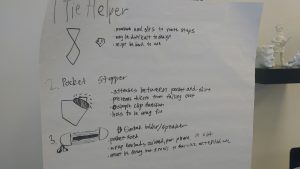
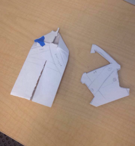 Paper Prototypes
 Arduino Software Application
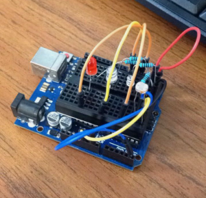 Test circuit for the final project
 The long awaited finished product
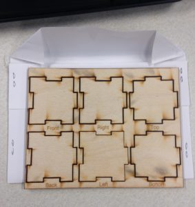 Smaller scale sample box pieces
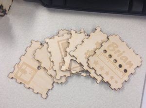 My pieces
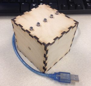 Sneak peek of the completed project
 < Outside view of the Fab Lab
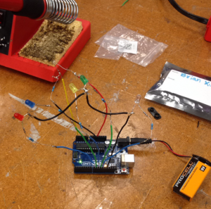 Arduino Circuit
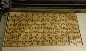 Laser Cut Tiger Puzzle