Digital Making Reflection

Before the class started this semester, I expected to learn 3D printing and work in a team with students from different interdisciplinary fields. Initially, I also thought that the course would be more technical; however, the course instead focuses more on design thinking and problem solving. The more technical offerings were found in the workshops we took at the Champaign-Urbana Fab Lab along with the AutoDesk Fusion 360 demonstration. Throughout the semester, I learned more about working in a team and more about the 3D printing terms and industry.

Here are the top things I learned through taking the course:

  1. Design Thinking is Key – Coming up with a great idea takes inspiration and hard work. How can we statements are helpful guidelines during the ideation phase. Try to find a problem that consumers are facing and create a prototype using that.
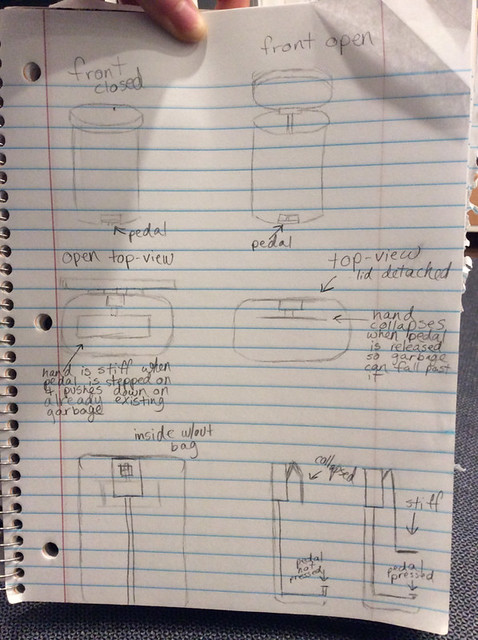
  2. Make Lots of Prototypes – There’s always a way you can improve on your product, so keep making prototypes. Test out new materials or new designs until the produce no longer runs into issues.
  3. Feedback is important – Receiving feedback from people on your designs is a crucial process throughout all phases. With constructive criticism, you can make adjustment to your designs and work on more ways to improve them. Learning how to provide feedback to others is also a great skill to have.
  4. Working with teams – In any jobs, you’ll be put in teams to tackle projects. Being a team player is a bulk of the work, be engaged during meetings to move the project forward and give constructive criticism. It’s also important to listen to the opinions of team members.  
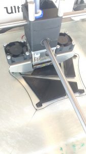
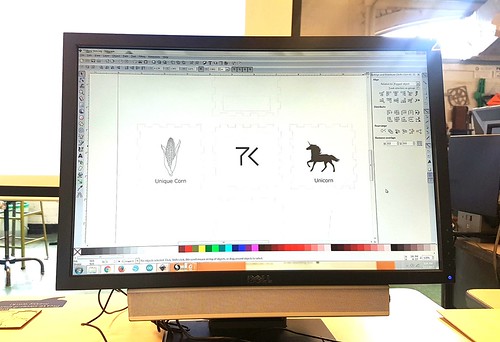
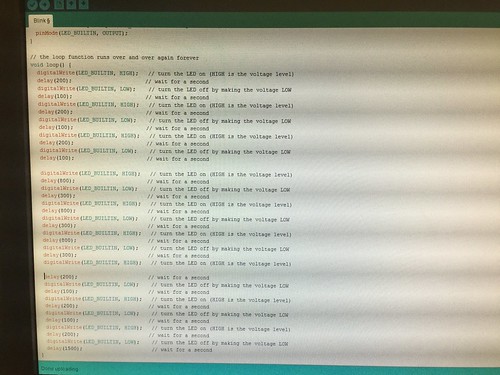
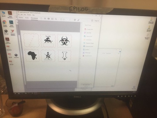
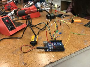
  5. Technical Skills – Every time I use the 3D printer, I am still mind blown. I am greatly to have dabbled in soldering, coding, Fusion 360, and other software. I definitely want to explore deeper into the software and skills I have acquired from the workshops.
  6. The Future is 3D Printing & Innovation – the potential of 3D printing is limitless. They are already being implemented in various field: tech, medicine, and fashion. It’s especially great to see the technology being used children to stimulate their problem solving skills and education. The same could be said for minorities and developing communities, where 3D printing is used to improve quality of life and educate.

It’s sad to know that the class has ended, but I will continue to utilize the skills and things I have learned in this course and apply them to future projects and in my career. I highly recommend other students to take this course and become a part of the Maker movement. Stop by and visit the Maker Lab or Fab Lab on campus!

Concluding Our Time at the Fab Lab

This week marked our last class at the Champaign Community Fab Lab, an innovative and dynamic maker space located on the campus of the University of Illinois. While in previous classes we have worked with soldering joints, encoding Arduino Uno circuit boards using Arduino’s open-sourced software, and wiring resistors and LED lights into breadboards, this week was the culmination of all our of efforts. We were able to finally assemble the photo resistor in its entirety. While in the past two weeks we took care of the actual photo resistor and its assembly, we still needed to create a structure that would house the part. In order to do this, Clinton and Julia, our two exponentially patient teachers, instructed us on the basics of Inkscape (a graphics editor similar to Adobe Photoshop), and on using the two laser cutters housed at the Fab Lab. The objective of utilizing these tools was to assemble a wooden, six-piece cube that would house the photo dependent LED light resistor. As mentioned, the software used to create the designs on the sides of the cubes was Inkscape, a completely free, open-source platform that appears to be user-friendly yet still able to make complex designs. Once the template for the wooden cube was downloaded, some manipulation was required in order to guarantee the fitting of the wood. In order for the laser to properly cut the wood, certain formatting and thickness adjustments had to be made. Using Inkscape, we traced black and white images taken from online, and, once finished, the PDF file was loaded onto the laser cutter. The laser etched the designs into the wood which created the downloaded images in a process called raster scanning, while also making the actual cuts to create the box (called vector scanning). The cutting process lasted just a few minutes, as subtractive manufacturing such as laser cutting can be considerably faster than additive manufacturing, like 3D printing.

Above is a picture of what the design of my wooden house looked like on Inkscape. While it cannot be discerned through this picture, there are very thin red lines outlining six intricate boxes. The red lines indicated to the laser cutter what needed to be vector scanned, while the black indicated a raster scan. Below is an illustration of the actual laser cutting process, during which the box outlines were being cut. The whole process, including both the design creations and actual cutting, lasted less than seven minutes, a stark contrast from the relatively lengthy time required for 3D printing.

These past three weeks have exposed to me all that the making world has to offer. While I originally assumed the making revolution focused squarely on 3D printing and additive manufacturing as a whole, this experience has brought about the realization that it is obviously much, much more than that. Going forward, I am excited to see how groups choose to incorporate what we have learned into their final projects.

Laser Cutting-Patience is a Virtue

This week wraps up the third and final session at Fab Lab. It gave us a sense of achievement as we were able to put together everything we’ve learned in the past 3 weeks into our final product–a personalized LED lightbox.

In this session, my group experimented with laser cutting. It’s a manufacturing technique that utilizes a laser which creates a beam of light to cut or raster on a panel of material. Common material used includes wood, acrylic plastic, and paper. For this project, we used Russian birch plywood.
inkscape-logo
17408115_1539942082690776_1406280540_o

To create our design for laser cutting, we used a program called Inkscape. It’s a free and open source vector graphics editor that’s similar to Adobe Illustrator. It was pretty simple and straightforward to use and we learned how to convert a bitmap image downloaded from the Internet into a vector image, so that no matter how you scale it, the edges will be just as sharp and not pixilated. In order for the lines to be cut later on with the laser, it has to have a thickness of 0.001”. As for raster engraving, the darker the shade of the image, the deeper the raster. After designing our images, we saved the file as PDF and brought it to the laser machine to start the cutting process.
17349346_1539942006024117_808098258_o

Staring at the laser machine while it did its work was actually entertaining, as shown in the video. We had to keep an eye on it the whole time to ensure it doesn’t catch on fire (which they said usually doesn’t happen, but who knows).

17342288_1539942052690779_1677394001_o

It took about 10 minutes for the machine to cut the 6 pieces as well as rastering 3 sides of the box. Fortunately, mine came out quite well though I had to use sandpaper to smooth out some of the edges. The next step was the exciting part–putting everything together. It took a lot of time and patience to assemble all the parts of the Arduino, LED lights, and wooden box with a hot glue gun, but in the end it was well worth it.

17380071_1539941996024118_881695424_o

Oh so magical.

17342144_1539942069357444_1538067418_o

Punny play on words 🙂 You go to U of I, you know it’s about the corn life.

17379895_1539942026024115_1941755771_o

My personal logo!

The major takeaways I’ve gotten after these 3 wonderful sessions at the Fab Lab:

  1. Technology is great and so much more than what we normally see. It’s not just about endless coding like what we usually imagine CS majors and software engineers do all day. The Fab Lab has taught me that it’s about combining different skills (coding, designing, soldering, fabricating, etc.) and sparking your inner creativity to make a variety of things, both for personal use and for the benefit of the society.
  2. Patience is a virtue. Yes, it’s triple cheesy but it’s true. I’m not kidding about the number of times I had to tell myself not to get too frustrated, whether it was soldering wires, assembling the LED, or gluing the final product together. This also applies to anything you want to achieve in life.
  3. Collaboration is key. You won’t go far trying to do something by yourself. Every person you meet knows something you don’t, so by sharing ideas with others you are able to accumulate a lot more knowledge which will help guide you in your creations.

Just to finish it up, I’m going to share a cool project that was done through Fab Lab: a 3D printed boombox. The board is written with Arduino language and can play music using an SD card and a 9V battery. I’m sure this bad boy will serve you well at a house party. 🙂

boombox

Week 7 Summary: Building on Our Skills in the Fab Lab

In Week 7 of the Digital Making Course, our community of Makers once again ventured over to the Champaign-Urbana Community Fab Lab. Similar to week 6, our class broke into our three groups to work on the next rotation in making the Blinker Boxes. However, since we were already familiar with the layout of the building and the resources available to us at the Fab Lab, we were able to hit the ground running. Once again, our three groups were split up to working on Coding with the breadboard and Arduino, soldering the electronics, or designing the press-fit boxes for laser engraving and cutting.

Our time in the CUC Fab Lab serves many purposes. First and foremost, it provides us the opportunity to practice skills that can help us with our own making endeavors. It is especially helpful for our project groups to develop a diversified skill set that we can utilize on our semester projects. The workshops at the Fab Lab also familiarize us with the technologies and physical tools available to us. Learning from the staff also helps us get a feel for the greater Maker Community and hearing about their personal projects helped us understand their skill sets and how each of them may be able to help with our projects. Finally, spending time in our own Maker Lab, the Fab Lab, and with all the staff and volunteers gives us a better idea of the Maker Movement that is revolutionizing businesses across the nation and around the world.

Supra

Team Supra’s Concept

As we keep going through the semester, we are rapidly approaching the design and prototyping phases of our semester projects. All of the project teams are refining their “How can we” statements while defining the actual problem they are looking to solve. Our first project idea submission was due on Wednesday of Week 7. To give you an idea on some of the concepts the class is working on, Team IJK is trying to help college students decrease stress by using indoor gardening. Team XNihilo is attempting to have busy professionals or college students drink more water. The MakerLAX is hoping to “help teenagers, young adults, and anyone else who struggles” tie a tie properly. Team Zerott is trying to improve patient satisfaction at hospitals. In Week 8, the project groups will be moving forward based on the feedback they have received. Once again we will be submitting our “How can we” statements, but this time we will include a concept details, key components of the solution, the capabilities of team members, outside resources for skills and fabrication tools, and any information resources identified.

Odelia Code

Odelia spent this week in the computer section of the Fab Lab code the Arduino for the Blinker Box. Odelia said, “This was my first time actually seeing a computer board up close and I was definitely quite surprised by how it looked. Personally, I thought that it seemed quite fragile and easily breakable. However, it was quite sturdy and it could hold quite a bit of force. Along with the Arduino board, the following things were included.” After setting up the circuit and trying to adjust the code, she found working with the light sensor was the most difficult part of the lesson. I think many would agree, as the range of values corresponding to which LED flashed depended on the specific sensor and how bright the part of the lab you were sitting in was.

Chase Soldering

Chase spent the class time in the electronics section of the lab soldering his LED’s together. Reflecting on the class , said “the instructional course ultimately proved to be very time consuming and required incredible delicacy, there is little doubt in my mind that this is a crucial tool in any maker’s arsenal of building tools.” For many in the class, this was their first experience with soldering. However, we all were able to pick up on tips and tricks such as using the “helping hands” or tape to hold wires down while soldering multiple pieces together. By the end of class, Chase and his group mates were able to wire the LED’s and sensor into the Arduino he programmed in Week 6 and the LED’s flashed as planned! Finishing off his post, Chase, like many, said he hopes to “incorporate soldering in some capacity” into the final project.

Kenny Design

The final phase of the Blinker Box is the making the press fit box. Kenny wrote about using the free Inkscape software to design his box. By taking images from the Internet and vectoring them using the Trace tool, the images became compatible with the laser. Kenny chose artwork from one of his favorite designers to put onto his box. Once it was finished, he said, “It was very rewarding to be able to see something you design on a computer come to life in a matter of minutes. There was something satisfying from watching it go back and for until your vision comes true.”

Kenny Box

All of our blinker boxes are coming together as we build on our skills at the Fab Lab. Week 8 will be the last class session in the Fab Lab but many of us will be back to work on our projects. Happy Making!


The Hands-on Intro to Digital Making. Part 2: Laser/Vinyl Cutting 7 Inkscape

LabLocationMd

CU FabLab. Located at 1301 South Goodwin Avenue, Urbana IL.

This week we got to return to my favorite part of the class for the second part of our three-part FabLab series. I got to immerse myself more in the hands on part of making. This time around I was more familiar and comfortable in the CUC FabLab space but I wasnt working with arduinos or electronics this time around. We were at first just shown the sample lasercut box and given back our kits below.
IMG_8043

At first, I was a little hesitant because I had thought that we would have to do the measurements by hand or use some form of Computer-aided drawing (CAD) but after listening to their explanation on the process of Laser/Vinyl cutting and engraving, I became more relaxed and interested in learning the tool they mentioned. Instead of using 3D CAD for prototyping like the usual, we used a graphics package called Inkscape to design the outline of each face as well as the graphics that we would engrave on the faces. Here we learned that the laser cutter performed two functions: Vector cutting which is when the laser cuts entirely through the wood or material and creates a blackened outline from the burn of the laser and the Engraving which is when the laser does not cut through the wood but etches a silhouette we created on Inkscape onto the wood in a darker unburnt shade. So essentially, laser cutting is a form of subtractive manufacturing where they take a flat piece of material and cut out shapes to be assembled into a hollow structure or skeleton of a solid object.

IMG_8049

Lasercutter vector cutting the outline through the wood

Before any of this we had to create the outline/shape on inkscape. There we learnt some of the basics of Inkscape and how to navigate the environment to use the tools available. We used a website to create the box press fit outline as it was much ore convenient and efficient than manually sketching it out. By putting the dimensions of the box in the website, we were able to adjust the settings to create our press fit box in a matter of minutes.  We imported pictures from the internet, and used tools to create our own shapes combining them into cool graphics to be engraved. Some of us even went further to create complex graphics such as the mythical creature I made which is a black panther with dragon wings as well as the “Illini light bulb” that I made which is a pun for the purpose of the lightbox we are making. But to convert these images and outlines, we had to create the Bitmap paths to turn them into silhouettes that the laser cutter could understand. By doing all these, I learnt how powerful graphics are in making designs and products more attractive and personal.The thing about the lasercutter environment below, is that it only recognizes specific colours: black as engrave space, red for vector cut path and white as material.

IMG_8044

The Lasercutter Final Print Environment

IMG_8054

My Final assembled press fit box. View 1

IMG_8053

My Final assembled press fit box. View 2

The cool thing about laser cutting is that not only is it fast and material efficient, it can be used on many other materials. the most common is wood and glass/vinyl but you can also laser cut metals, paper, foam, cork, silicone and so on. You can learn so much more here at this link. The Stanford Product Realization Lab is making great products there and exploring much more materials. But the most impressive thing to me is the innovative use of lasercut patterns to make flat materials curved or bendable. They way they do this is by laser cutting thin lines and holes in the area that is desired to be flexible in such a way that there would be more freedom for that section to be less rigid and be able to stretch and hence be flexible.

Now with all this the final outcome for our lightbox should look like the sample below. I am looking forward to being able to incorporate this into our project this semester.

IMG_8050

Sample final product for the lightbox.


Week 6 Summary: An Exploration of the Fab Lab Opportunities

This week we engaged in the second phase of a continuous three-part series meant to offer exposure to the myriad of activities offered at the Champaign-Urbana Community Fab Lab. The Fab Lab, although the majority of the class was unaware of its existence prior to this semester, is a leading-edge open and collaborative workspace for design, creation, and printing through the use of computer-driven technologies, such as 3D printing, lasering, inkscape, and soldering. Below is a picture of one of the spaces within the workshop.

One of my favorite aspects of the Fab Lab is its openness to the entire community, irrespective of whether the makers are students or local community members. Everyone is welcome and simultaneously given the resources to collaborate, share, and implement their ideas. Since the making space offers such a vast array of opportunities to its various users, the class was divided into three separate groups during our first session, with each group rotating between the three main functions of the lab: laser cutting, soldering, and coding.

In Brian’s most recent post, he examines the laser cutting portion of the project. The objective of this part was to assemble the wood cube that would house the photo dependent LED light resistor. The software used to create the designs on the sides of the cubes was Inkscape, a completely free, open-source platform that appears to be user-friendly yet still able to make complex designs. Once the template for the wooden cube was downloaded, he initially needed to consider some alterations to guarantee the fitting of the wood. In order for the laser to properly cut the wood, certain formatting and thickness adjustments had to be made. Using Inkscape, Brian and the other members of his group traced images taken from online, and, once finished, the PDF file was loaded onto the laser cutter. The laser etched the designs into the wood which created the downloaded images, while also making the actual cuts to create the box. The cutting process lasted just a few minutes, as subtractive manufacturing such as laser cutting can be considerably faster than additive manufacturing, like 3D printing. Brian’s finsihed creation can be seen below.

Carter’s weekly reflection focused on the soldering aspect of the project. While the initial instruction appeared to be very time consuming and required immense precision, concentration, and delicacy, soldering as a tool in the making and design process can be incredibly powerful and handy, as it offers certain advantages to a product that otherwise would not be available. Soldering allows for more accurate and uncluttered connections between various electronic parts, such as wires, resistors, and other components. An additional benefit of soldering is the ability to maintain the original shape of the soldered metals, considering that the solder has a much lower melting point than the adjoining metal. Since the fusing occurs at much lower temperatures (albeit still incredibly hot), the metals that are being connected do not warp in shape or size, nor do they melt. Lastly, soldering allows for the joining of multiple wires using a single focal point. This can allow electricity to be conducted, as all the wires have been bonded together. Below is a picture of Carter’s finished soldered Arduino circuit board and light dependent resistor.

Charlene’s post focused on the coding of the Arduino Uno circuit board, using Arduino’s open sourced software. Arduino’s simple platform allows for makers with only basic coding experience to still utilize the immense functionality of the technology. Her group was tasked with coding specific behaviors into their widget. In this case, the object that was being encoding was a photo resistor (light dependent resistor) with LEDs. By connecting the LED lights to the light resistor and being guided through some of the basics of the Arduino code, the LED lights extinguished in the presence of light and flashed during times where there was no light (when it was covered by a hand, for example). This first exercise with the Arduino technology was simple enough for us as first-time users to comprehend, yet was still an applicable and useful first attempt at the software, and definitely something that could potentially be incorporated into our end of the semester final projects. Personally, having the ability to view tangible, physical result of our efforts was something that felt gratifying. Charlene’s final product for this phase of the project is pictured below.

While each group has been focusing on a specific activity, we can universally agree that the experiences at the Fab Lab have been invaluable to our making journey. We are constantly attempting to apply what we are learning to not just our semester projects, but also outside of the classroom. I look forward to the rest of our time at the Fab Lab, as well as the rest of the semester!

Week 7: 2nd Week at the Fab Lab (Laser Cutting)

Aside

For our second visit to the Fab Lab, each group switched stations to work on a different portion of our final project. This week, I attended the Laser Cutting session. Though the workshop is somewhat secluded towards the back of the Fab Lab, it certainly shines through as one of the more unique creative processes the Fab Lab has to offer (no pun intended).

In my last workshop, we focused on designing the physical circuit for our light-sensitive boxes. This week, we continued with moe hands-on work dedicated to making the appearance of the project aesthetic and to our liking. By using specifically designed software, we were able to create layouts for our boxes that we could customize. We first gained the template after entering our desired dimensions into an online resource, and then imported that file onto the lab computer software Inkscape to customize them. We were able to select images online to use as stencils for the panels. The images had to be completely black & white, as well as properly pixelated. The laser cutters are incredibly precise, and are able to stencil out wood portions with cuts of down to .001 m in width, resulting in flawlessly fitting pieces and stellar quality of silhouettes. One of the most amazing bits of all this, is that each person’s cuts only took approximately 20 minutes maximum, way faster than a conventional 3D printer. While it is certainly a sight to see something create out of nothing, some don’t realize that you can also achieve great designs by taking away from what you already have.

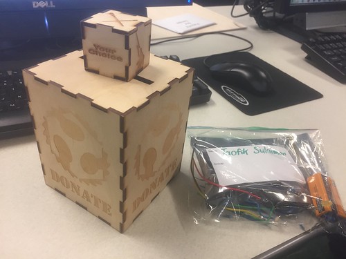
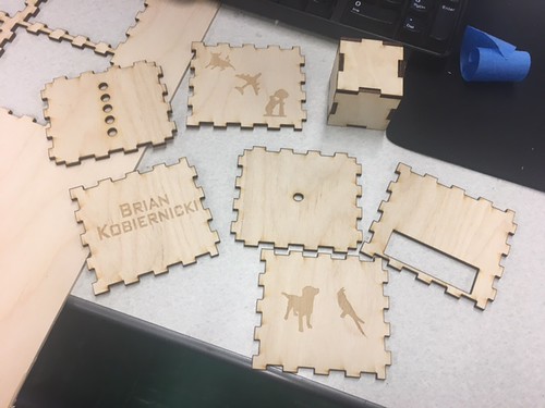
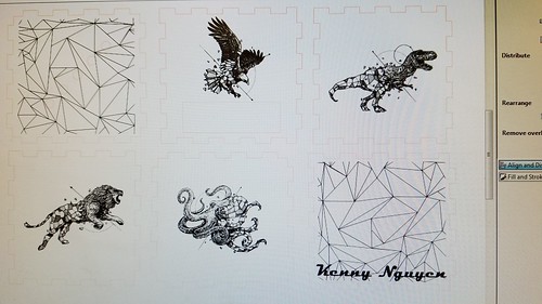
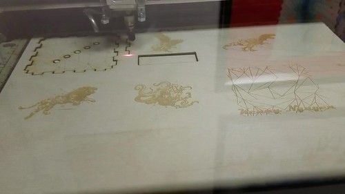
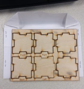
Smaller scale sample box pieces
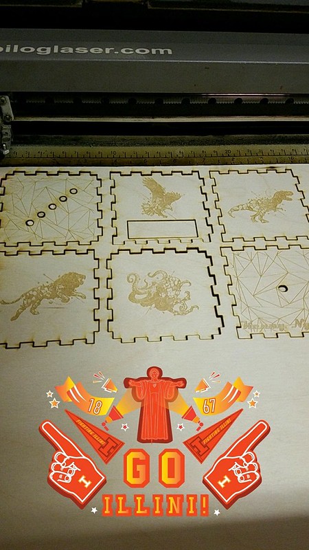
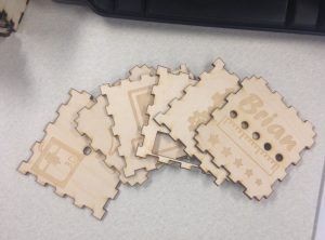
For my custom designs, I chose each side to represent a field of engineering/design as I am an engineering major. Four sides included images reminiscent of electrical, mechanical, and computer engineering, as well as architecture. The underside of the box features a 3D printer silhouette as well as that of a laser cutter, the two main methods of design that my group will probably use in our final project. The remaining side just has my name with a special measurement system composed of a ruler image and different sized stars to represent the brightness of the LEDs.

My pieces

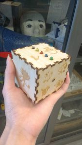
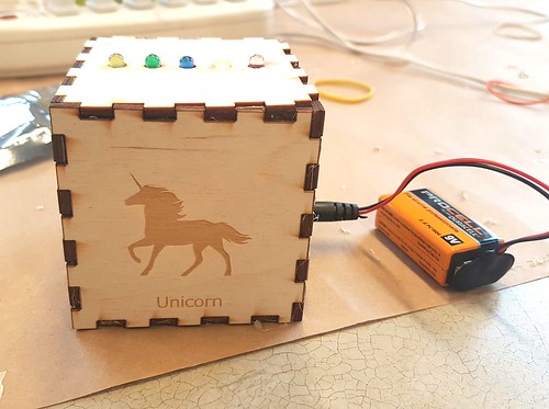
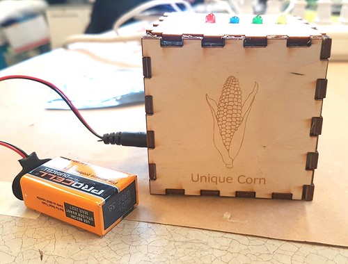
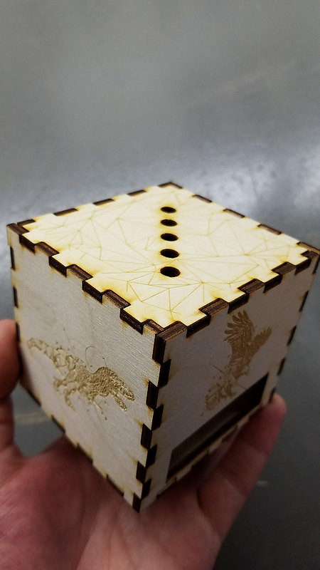
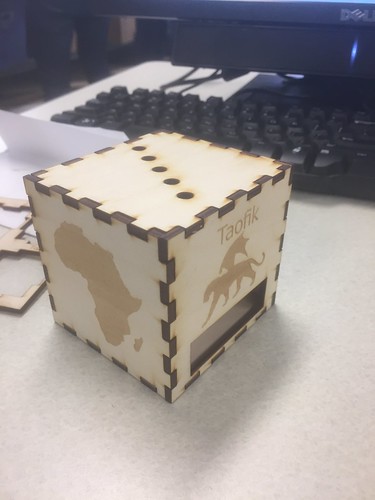
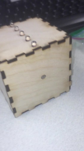
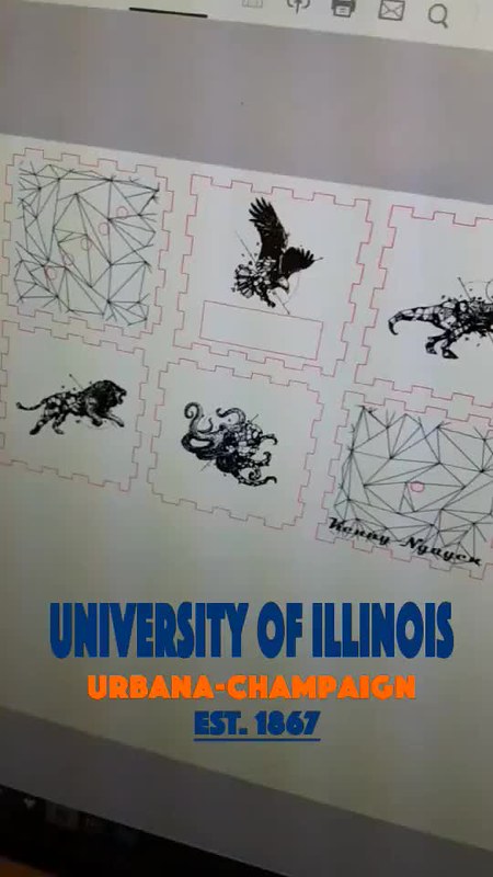
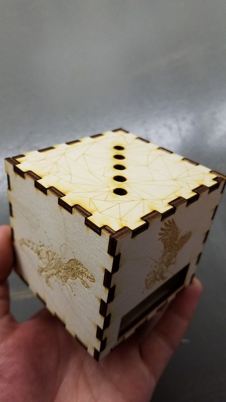
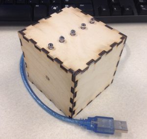
Sneak peek of the completed project

Now that I’ve completed both the physical portions of the workshop, I’m excited to take part in the coding session next week, where we will program the Arduino with the desired code to allow it to respond as we want it to. I’ve thoroughly enjoyed these Fab Lab sessions not only because we get to create a custom project for ourselves to keep in the end, but we also get to see multiple types of engineering and designing intertwined (specifically electronics, mechanics, and programming) into a single project. It’s been a fantastic experience to work with all these different processes, and I’m hoping that we can incorporate every one of them into our final project.

Inkscape and Laser Cutting

The second session at the FabLab this week meant that we were at a new stage for our light receptor boxes. Last week we had the pleasure of soldering the circuits together and testing it on the Arduino units. This week our group went to the laser cutter to create the box in which our project will be encapsulated in. We utilized a free software called Inkscape which is similar to Adobe Illustrator but I found it a little easier to use. We started off by learning the basics of taking an image from the internet and then vectoring it to be able to get the black lines out through the Image Trace option and that allowed us to make basic images into vectors that we can work natively on the software.

20170306_151900

This made it very intuitive to be able to take any image with defined black and white borders and make it into a vector so we are easily able to manipulate the points and add or subtract portions of the image. We obtained the box layout from a website that the FabLab provided us and then added our own designs. This was the outcome of me scouring the internet for my favorite graphic designer from the Philippines, Kerby Rosanes.

20170306_153427

Upon finishing the files and layout, you transferred the document as a PDF file to the printer and I was using the EpiLogue printer which is a very strong one that can cut a variety of materials as well as thicknesses. You had to make sure that the colors and sizes of the cuts were 0.001 in and that the color was in RGB mode with 255 for Red and 0 for everything else. The raster aka engraving could be black and any size. The laser cutter was very precarious and we had to make sure that the settings were 100% accurate.

Snapchat-1358921269

Here you can see a time lapse I had made through the rastering process.

20170306_155258

It was very rewarding to be able to see something you design on a computer come to life in a matter of minutes. There was something satisfying from watching it go back and for until your vision comes true. After the printer is able to raster everything, it begins the cutting process which I also speed up the cutting time.

20170306_160446

Here you can see the final cuts and it is all done for me to assemble.

Snapchat-96312379

The picture below shows me assembling the box without the electronic components in it yet and so I thought it looked very cool and can not wait to combine everything together next week after we learn to code the Arduino.

20170306_161242

A helpful article I found while using the laser printer was found on Instructables with 10 helpful tips and tricks. Going forward I am excited to be able to use the laser cutter for our final project as it is less intimating as I thought it was. I will also probably use this tool for other projects too since it is fairly easy being able to use this tool.

The Hands-on Intro to Digital Making. Part 1: Circuits and Soldering.

LabLocationMd

CU FabLab. Located at 1301 South Goodwin Avenue, Urbana IL.

This week was definitely my favorite class session, because I am a person who loves getting work done physically and having a physical product in my hands. After hearing Jeff Ginger – the director of CUC FabLab – tell us about the lab in week 2, he gave us a great tour through the space where we got to go in as part of a series to get trained on and work with the many great tools and resources there ranging from 3D printing, to digital embroidery and every thing in between such as the biohacking space and laser cutter. It was also interesting learning how it all tied in with a Fablab movement/Network of FabLabs across the globe. Seeing the place in person was definitely more inspiring as they turned a place that could be considered run-down into an environment where ideas and creativity are not just born but brought to life. Its very astonishing how much is possible and available through the lab, they had a section for each of the above mentioned and set up classes to teach each of these concepts.

@Fab Lab splash-b8d8cb4fbb

Different facets of the FabLab.

After the tour we, were split up into groups to partake in these classes to dive into one of these facets. I started with circuits and soldering using the given starter kit shown below. It consisted of an arduino uno board, batteries to power it, a photo resistor/resistor that changes its resistance according to the amount of light that hits it,

IMG_8006

Starter Kit

So with these resources, we will create a light sensing box that changes color the darker it gets around the sensor on the box. We were taught the basics of soldering – which means to join two wires using a hot-tip soldering iron and tin metal as a joint -then setting up the wires in the right connections with the LED lights and resistors, and finally plugging them into the arduino boards that were preset with the code needed for the final product. I enjoyed my time working on these so much that I bought some parts to work on my own personal projects and thats one of the effects that the FabLab has on people – inspiring the maker mentality to people that visit.

IMG_8008

IMG_8009

My Final Circuit

And now that we will have these skills and be familiar with these resources, we will be able to apply them to our own group projects due at the end of the semester. I am looking forward to the next two weeks where I will learn how to use laser cutters, write Arduino code and bring them all together. And I suggest everyone gets involved in the fablab nearest to their communities. Here’s links to learn more about Fablabs and where to find the nearest one. Link 1. Link 2.

Week 6: First Visit to the Fab Lab

This week, we paid a visit to the surprisingly out-in-the-open Champaign-Urbana Community Fab Lab; a free community center-like makerspace open for anyone. The Fab Lab is aptly named as the inner workings of the building are almost like a laboratory filled with fabulous creations by the volunteers and others who happen to stop by. Unlike our Digital Making Lab, it contains not only 3D printers, but other varieties of technology designed for the specific purpose of creation. These include sewing machines, paper cutters, laser engravers, and soldering stations. The lab contains a plethora of methods for people to express their creativity; it’s a shame that it is not very well known.  
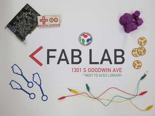
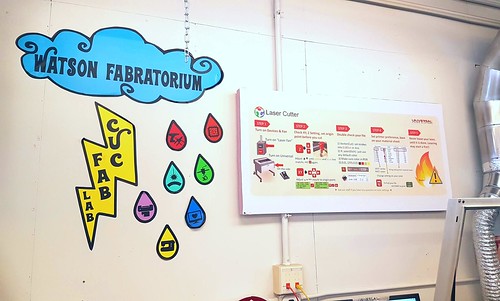
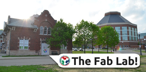
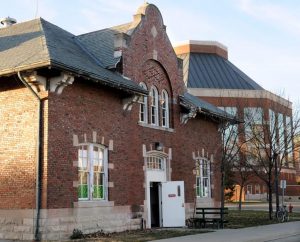
< Outside view of the Fab Lab
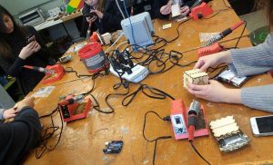
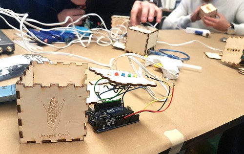
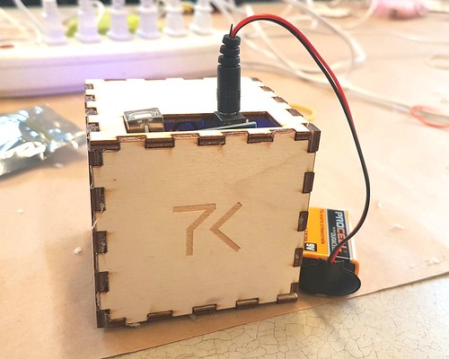
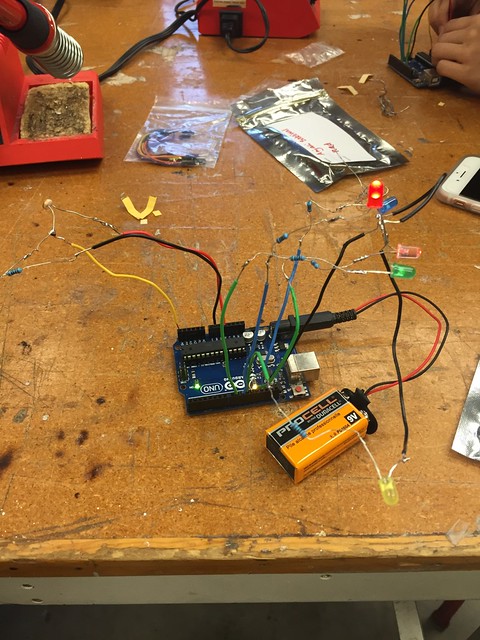
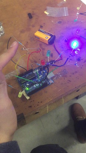
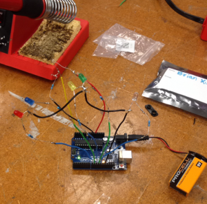
For the first week here in our 3 part saga in this lab, one person from each of our groups was assigned to a station in the lab where we would participate in a different workshop to make something out of nothing. For my personal station, we worked in electronics. I chose this because as an electrical engineering major it was definitely in my all you expertise and I knew that I would be able to learn something to improve upon. Our project was creating a type of light-sensing electronic circuit using LEDs, a photocell resistor, and an Arduino. Depending on the amount of light sensed by the resistor, a different color LED would light up. If no light was sensed, then all the LEDs would turn on. The project involved looking at some schematics and quite a bit of soldering, and the end result as it currently stands (an Arduino board with a bunch of wires and LEDs branching everywhere) did not look so appealing, but the functionality was the true beauty of it. Plus, we should be able to improve upon and make the design “prettier” in our next workshop. The other two groups were split into those working with laser cutters and coding in the computer lab portion of the Fab Lab. Laser cutting is another type of 3D printing in a sense, but in a way opposite to the norm. Instead of starting with nothing, your starting material is already there. You just need to decide upon a design and what portions you wish to cut out rather than add on. The results are stunningly precise. And while coding might not seem as glamorous as the other two activities, it is the basis of modern day electronics. Virtually every device for use by citizens requires some programming: phones, computers, televisions, and the 3D printers we use in our lab. It may not inherently make some visually stunning object, but without it we wouldn’t be able to use the machines that make those objects in the first place. All in all, these activities were extremely enjoyable to spectate and participate in, and in doing so we’ve gained knowledge of more methods for our use in not just our final project, but Making as a whole.

 Arduino Circuit

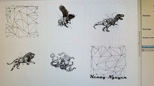
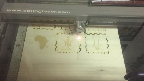
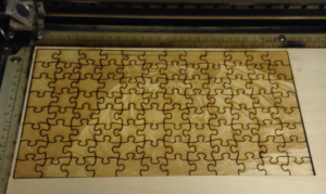
Laser Cut Tiger Puzzle