Concluding Our Time at the Fab Lab

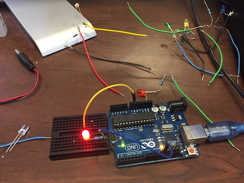
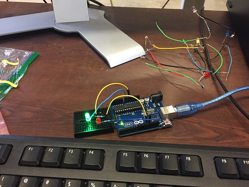
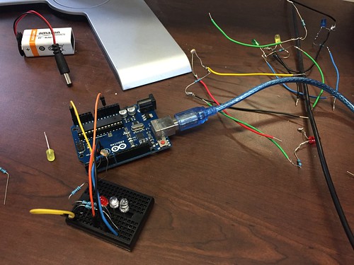
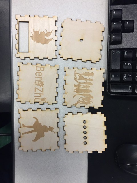
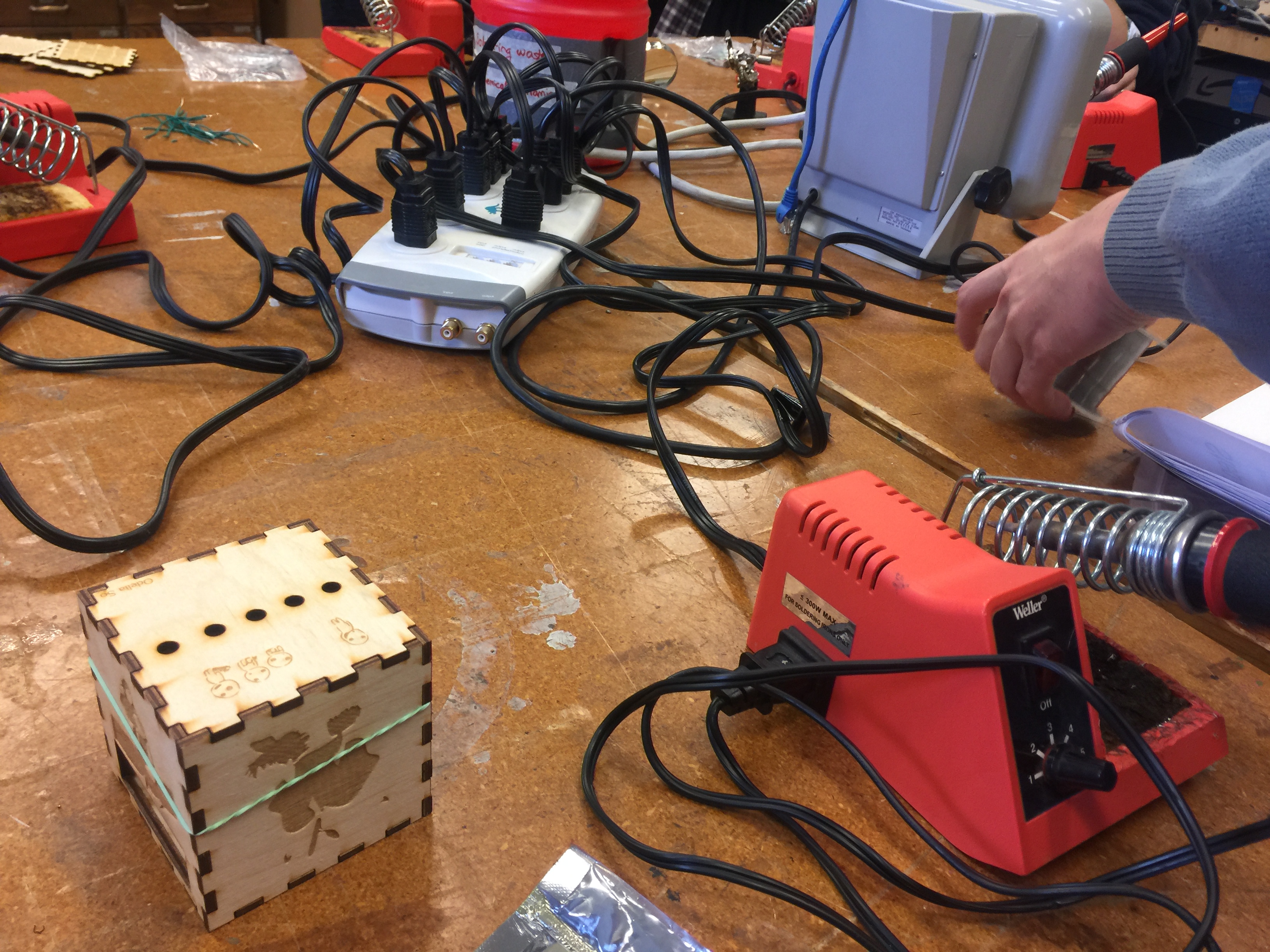
This week marked our last class at the Champaign Community Fab Lab, an innovative and dynamic maker space located on the campus of the University of Illinois. While in previous classes we have worked with soldering joints, encoding Arduino Uno circuit boards using Arduino’s open-sourced software, and wiring resistors and LED lights into breadboards, this week was the culmination of all our of efforts. We were able to finally assemble the photo resistor in its entirety. While in the past two weeks we took care of the actual photo resistor and its assembly, we still needed to create a structure that would house the part. In order to do this, Clinton and Julia, our two exponentially patient teachers, instructed us on the basics of Inkscape (a graphics editor similar to Adobe Photoshop), and on using the two laser cutters housed at the Fab Lab. The objective of utilizing these tools was to assemble a wooden, six-piece cube that would house the photo dependent LED light resistor. As mentioned, the software used to create the designs on the sides of the cubes was Inkscape, a completely free, open-source platform that appears to be user-friendly yet still able to make complex designs. Once the template for the wooden cube was downloaded, some manipulation was required in order to guarantee the fitting of the wood. In order for the laser to properly cut the wood, certain formatting and thickness adjustments had to be made. Using Inkscape, we traced black and white images taken from online, and, once finished, the PDF file was loaded onto the laser cutter. The laser etched the designs into the wood which created the downloaded images in a process called raster scanning, while also making the actual cuts to create the box (called vector scanning). The cutting process lasted just a few minutes, as subtractive manufacturing such as laser cutting can be considerably faster than additive manufacturing, like 3D printing.

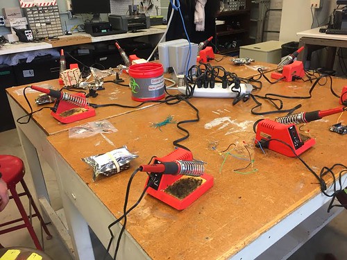
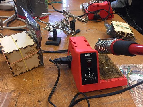
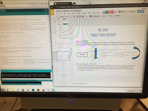
Above is a picture of what the design of my wooden house looked like on Inkscape. While it cannot be discerned through this picture, there are very thin red lines outlining six intricate boxes. The red lines indicated to the laser cutter what needed to be vector scanned, while the black indicated a raster scan. Below is an illustration of the actual laser cutting process, during which the box outlines were being cut. The whole process, including both the design creations and actual cutting, lasted less than seven minutes, a stark contrast from the relatively lengthy time required for 3D printing.

These past three weeks have exposed to me all that the making world has to offer. While I originally assumed the making revolution focused squarely on 3D printing and additive manufacturing as a whole, this experience has brought about the realization that it is obviously much, much more than that. Going forward, I am excited to see how groups choose to incorporate what we have learned into their final projects.

Week 8: Putting Together the Puzzle

Today we are back at the CU Fab Lab to continue our workshop rotation. Last week I learned how to use code for Arduinos. This week, I get to learn soldering. I was really intimidated by the equipment in the workshop. Last week, I read someone’s post about how the machines can get up to 800 degrees Fahrenheit! I am so clumsy that  I’m afraid I would burn myself and add to what my family calls my “Hall of Scars”(see picture below, it’s not pretty). However, I’m willing to put my best foot forward and hope to the heavens I don’t hurt myself.

Hall of Scars:
scar


When I got to the lab we went to the soldering room. There was a black board with a few warnings about soldering (see below). Apparently, not only were we working with hot irons, we were also working with toxic items, as the solder is made of lead. I had a bunch of butterflies in my stomach.

Whiteboard Warning:
board

Workshop space:
klerj

My Working Station:
stata

Soldering Iron:
iron

Cleaning Pad to clean solder off iron:
clean


Before we began, we were asked if anyone knew how to or had experience soldering. Not a single person raised their hand. I’m glad I wasn’t alone. The instructor told us that we will be soldering together a circuit to make sure our wiring did not come loose inside of our blinking box. We would be making this circuit using the knowledge we learned about wiring,circuitry and Arduinos

Example of what we were going to make:
LED


Before we could solder two objects together, we had to make sure that the wires were touching so that the electrical current can travel seamlessly around the circuit. If the wires are not soldered together while they are touching, they will not pass the current through the circuit. I found soldering somewhat difficult, until the instructor told me to use the soldering iron to heat the wire before adding the lead solder to it. We made 5 LEDs which had their negative ends wrapped with a resistor and the resistor wrapped to a jumper wire. We then had to connect the other ends together using a black jumper wire and solder it. Once we were finished with that, we had to take a break due to the lead fumes in the room. To finish our soldering, we soldered on the ultrasonic distance sensor to the black jumper wires connecting the LEDs. Finally, we hooked up the circuit to the battery-powered Arduino which was coded in last week’s workshop. ‘

My First Solder:
solder

LED soldered to a resistor and jumper wire:
1unit

5 LEDs together:
mine

Ultrasonic Distance soldering:
dist

Circuit attached to Arduino:
arduino

Live Action Circuit on Arduino:
Animated GIF  - Find & Share on GIPHY

This soldering workshop really helped me understand the use of soldering. While I was participating in the workshop I thought of how for our final project idea, we will most likely need to solder wires together. Our idea was to make a hydration band or fitbit attachment which would blink when the sensor is triggered. Soldering wires could possibly be one of the ways in which we could keep the wires in a circuit. Additionally, while I as soldering, I wondered what other cool projects could utilize soldering. I looked some up and the links are below.

Cool  Soldering Projects:

Soldering Tips and Tricks: https://www.youtube.com/watch?v=xrVCkEoY_8M

At the end of the class we hot glued our boxes together and glued the LEDs into the holes. Here is the end product. (last white LED was broken and I had to run to class before I could fix it)


Animated GIF  - Find & Share on GIPHY

Animated GIF  - Find & Share on GIPHY

Week 8: Coding Session & Integration

I have to say the third session of the three-week workshop is the best and most intensive one. This workshop breaks into two parts. At first, we learnt how to code the program for the most of workshop; then we combined the wooden shell, Arduino, LED lights, and light sensor together to get an integrated and functional unit.


At the very beginning, we used one single LED lights and one extra circuit board to test simple program we made. As you can see from the picture below, I connected the 5V power source to the positive side of the LED light. There was a resistor placed along with the negative side of the LED light.

IMG_3827

The first challenge for us was to send SOS signal in the form of Morse code. SOS in Morse code is a continuous string of three dots, three dashes, and three dots. To express the SOS signal with LED lights, I adjusted the time of LED flashed. I coded the program that required LED lights to flash quickly three times, slowly for another three times, and then quickly for three times. From the eye of an observer, he/she could easily discover the form of “…—…” and interpret the signal as “SOS”.

IMG_3825

The second challenge for us was to make two LED lights flash alternatively. Although I knew that I should make one LED flash quickly and another one slowly, I could not transform my idea into actual code. Fortunately, after I thought for about 5minutes, the instructor reminded me to create two objects so that I could input different commands for each LED lights. This picture below displayed the moment that I successfully made the two LED lights flash alternatively.

IMG_3828

The third challenge was to integrate the photo sensor into the circuit and use the sensor to control the LED lights. This challenge should be tough. However, instructor gave us the blueprint of the final circuit because most of us did not have solid background in electric engineering. Following the blueprint, I quickly connected these components. The short video showed the functionality of my circuits.

IMG_3830

Now, it was time to combine all the work we had done in the past three weeks. It was supposed to be easy since all we needed to do was to place the circuit in the shell and use the glue to solidify the box. Well, unexpected things happened. The board with one hole and the one with six holes should be attached together so that the photo sensor could work properly. Somehow, the shapes of these two boards I had were identical, which meant that these two board had to be placed parallel to each other.

IMG_3798

Thus, I had to put the photo sensor and other four LED lights on the same plane. Though a little bit frustrated with the final result, I did learn how to solder the circuit, design the pattern, and code the program for Arduino in the last three weeks. I believe that I will use the knowledge a lot from these workshops for the final project.

Week 8: Skill Set and Soldering

This week at the FabLab we wrapped up the workshop sessions. My team, the white team did soldering this week. Before this week’s workshop, I’ve seen my dad solder wires together to improve “circulation” of the wires, so I already felt like I did have some knowledge in this area. However, in truth, this week was my first week in getting hands-on experience with it.

Soldering station

To be totally honest, out of all three workshop stations, my favorite was the laser cutting station due to my overall familiarity with the concepts of the machine, as well as the usage of the software. This week’s station was probably the most frustrating and difficult area for me. The combination of needing nimble, yet sturdy fingers to twist the wires together, the potent smell of the metals melting together, as well as the fragile and easily breakable wires made the whole process mentally straining. The constant need to be mindful of the positive and negatives of the LED lights, as well as the much-needed patience really took a toll on my attitude towards soldering, and by the end, I felt ready to give up and never touch soldering again. To add fuel to the fire, because of my twisting and turning of the wires, the connections constantly broke to a point in which some of the connections were unrepairable. Because of this turn of events, I was unable to successfully created the LED box that included the soldering of the lights and photoreceptors. Since I broke most of my connections toward the end of the class, I had no time to redo the soldering and was forced to create a prototype LED box with the breadbox and the Arduino. As much as I don’t like soldering, this skill is very important to have knowledge of. Thanks to CUC FabLab, I am now able to solder wires together (even if I’m terrible at it).

In the end, no matter how must frustration or hatred I had for a specific “step,” the workshops that we learned from were definitely really helpful in our group projects and will help us start finalizing what process and skills are needed for the project. Furthermore, not only did we gain three new skill sets to use but also gained insight to our abilities in each skill. By analyzing these interactions, we were able to tell which part of building our future project prototypes was our strong point and which was our weak point. For me, it was obvious that designing and laser cutting was my strong suit, while soldering was hands-down my weak suit.


Final Week in the Fab Lab: Coding with Arduinos

This week we faced the cold and snow as we headed to the Fab Lab for our final session of our 3-week long workshop at the Fab Lab. After working in the electronics area to solder, the laser area to make the press-fit box housing, it was time to work in the coding area at the front of the Fab Lab.

Assisting our group with the Arduino portion were Fab Lab staff members Andrea Vozar and Alexis Papak. After an introduction to the interface we would be using to practice our coding, we started taking out all the components in our kits. To familiarize ourselves with the basics, we set up a simple circuit and opened up some example code that would cause an LED to flash on and off. We were than challenged to change the code so that it signaled the SOS message Morse code. After adding a few lines and changing some values then uploading the new code to the Arduino, I was able to successfully make the LED signal SOS. Then we were challenged to add a second LED and code it so that the lights alternated flashing. After changing the existing code and adding more lines to accommodate two separate LED’s, the lights alternated flashing.

IMG_1137

Once we were comfortable with our introduction to coding, it was time to start working on the Blinker Box. We followed a schematic to assemble our soldered LEDs into the right pins, ground, and power source. Then well pulled up the coding for the light box and uploaded it to the Arduino. Now we had to test the photo resister to determine the range of light intensity that was being sensed. After a few attempts of trial and error, I was able to identify an appropriate range for the LED’s to light up at and eventually cycle through flashing. Finally it was time to assemble the box. Using the press-fit cutouts from last week, I put the LED’s and photo resister through their respective holes, and then assembled the box around the Arduino. After 3 weeks of hard work, the project was completed!

IMG_1138

Over the past three weeks, working at the Fab Lab provided a solid foundation of 3 different areas of making. Not only do we have a tangible object to show off our learning, we are also comfortable working in the fab lab and can now use what we learned on our group projects and hopefully our own personal projects. To help with personal or the group project, I found Hackster.io, an online community geared towards helping people learn about hardware. You can search difference projects by proficiency level, application type, hardware unit, or many other options. it reminds me of Thingiverse in that you can search and use product categories as well as the community platform it provides.  For the group that is considering Hydroponics product, I found this project using Arduino and Raspberry Pi, which may be helpful.  The Arduino website also has a great collection of resources for learning the various Arduino products, programming, and offers several tutorials to work through.  Happy Making!