Digital Making Reflection

Before the class started this semester, I expected to learn 3D printing and work in a team with students from different interdisciplinary fields. Initially, I also thought that the course would be more technical; however, the course instead focuses more on design thinking and problem solving. The more technical offerings were found in the workshops we took at the Champaign-Urbana Fab Lab along with the AutoDesk Fusion 360 demonstration. Throughout the semester, I learned more about working in a team and more about the 3D printing terms and industry.

Here are the top things I learned through taking the course:

  1. Design Thinking is Key – Coming up with a great idea takes inspiration and hard work. How can we statements are helpful guidelines during the ideation phase. Try to find a problem that consumers are facing and create a prototype using that.
  2. Make Lots of Prototypes – There’s always a way you can improve on your product, so keep making prototypes. Test out new materials or new designs until the produce no longer runs into issues.
  3. Feedback is important – Receiving feedback from people on your designs is a crucial process throughout all phases. With constructive criticism, you can make adjustment to your designs and work on more ways to improve them. Learning how to provide feedback to others is also a great skill to have.
  4. Working with teams – In any jobs, you’ll be put in teams to tackle projects. Being a team player is a bulk of the work, be engaged during meetings to move the project forward and give constructive criticism. It’s also important to listen to the opinions of team members.  
  5. Technical Skills – Every time I use the 3D printer, I am still mind blown. I am greatly to have dabbled in soldering, coding, Fusion 360, and other software. I definitely want to explore deeper into the software and skills I have acquired from the workshops.
  6. The Future is 3D Printing & Innovation – the potential of 3D printing is limitless. They are already being implemented in various field: tech, medicine, and fashion. It’s especially great to see the technology being used children to stimulate their problem solving skills and education. The same could be said for minorities and developing communities, where 3D printing is used to improve quality of life and educate.

It’s sad to know that the class has ended, but I will continue to utilize the skills and things I have learned in this course and apply them to future projects and in my career. I highly recommend other students to take this course and become a part of the Maker movement. Stop by and visit the Maker Lab or Fab Lab on campus!

BCC Creations – Door Sitter: Our Experience in Making

Our journey of creating the Door Sitter was challenging yet intuitive. Though the three of us in BCC Creations were not engineers, we had used our resources, research and knowledge to create an efficient product.


Prior to choosing to create the Door Sitter we went through a couple of ideas in our brainstorming process. We had first started out with identifying problems that were occurring in our own lives or to those around us. Vishal had stressed on using the Design Thinking Method which was a problem-solving process that allowed us to build up ideas with no limitations. Our first idea was based on our teammate, Carter’s experience with the recreational facilities on the U of I campus. He had noticed how many of the sporting balls were not at the correct PSI and having a decide to test it rather than manually doing it would be efficient. Thus, we decided to create a product to regulate a sporting balls PSI and pumping the ball to the correct amount. However, the more in-depth we got and furthered our research we realized that the product itself would be very complex and the pricing of it may not be suitable for the target consumers. Furthermore, we thought the product would worsen the problem and reduce the efficiency and we wanted to create a product that would be beneficial for more consumers.

Our next idea had helped lead us to our final idea, a Chores Alert System. We thought it would be useful to those in the dorms with roommates, they would be alerted through a text whenever a chore needed to be accomplished. Though we all liked the idea we had continued brainstorming for more possibilities which led us to the Door Sitter. All three of us lived in apartments and had the realization that when we left during school breaks we had no way of checking for breaking and entering which had happened to many of our friends. So we came up with the idea of creating an affordable yet efficient alarm for an apartment that would be able to detect an intruder and sent a text message to the roommates of the apartment.

Making


Once we finished brainstorming and settled on our problem to solve, it was time to determine how we were going to solve that problem, and how we could actually make that solution work.  Fortunately for us, we had the MakerLab and Fab Lab at our disposal, not only for the physical components but also their expertise.  

We knew that we wanted to 3D Print the housing for the system since we were familiar with the MakerLab, knew we could have multiple iterations, and the general low cost of 3D Printing.  Before we could start designing the housing, we had to know what physical components our alarm system would need to function.  Only after we settled on the technologies and hardware we were using could we design the housing.

Hardware

IMG_1514

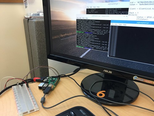
Initially, we planned on using an Arduino since we had used one and had experience programming it from our Blinker Boxes during our time at the Fab Lab.  We thought we could use an Arduino with a bluetooth module to send notifications, but later decided to use a Raspberry Pi with Kootek Wifi adapter from the Maker Lab.  To detect motion, we used an ultrasonic sensor from the Fab Lab.  This allowed us to detect motion within a specific range that we were able to physically adjust to about 10 feet at a 120 degree angle.  We also picked up male to female jumper wires to connect the Raspberry Pi, sensor, and breadboard together.  We powered the device through mini-USB rather than a battery, and ultimately decided against the piezo sound buzzer.  To interact with the Raspberry Pi, we used a keyboard, mouse, and monitor from the MakerLab.

Software

2r7wkes

Once we acquired all the hardware for the security system, it was time to make the system actually work.  We first had to load an operating system (Raspberrian) onto the device so that we could put in the Python code.  We were fortunate to have Charlene’s friend lend us his technical skills with the programming.  We used Twilio as a service to send the text message notifications to our phones when triggered by the motion sensor.  To design the housing, we initially started using Fusion 360 since we had used it for the tutorial homework and our in class workshop with Jeff Smith, but we instead used Tinkercad for its simplicity.  Although it is a relatively simple program, Tinkercad provided all the functionalities we needed, with far less complication.  

The entire “making” process flowed very well.  As the software was being programmed, we were simultaneously physically putting the hardware together.  Once we knew how much space the hardware was taking up, we were able to design, print, and refine the housing.  The MakerLab provided a great meeting place to work on the project together in addition to supplying the Arduino, wifi adapter, keyboard, monitor, power cord, and mouse.  The Fab Lab was also a great outlet to receive advice from and supply us with the sensor, breadboard, and jumper wires.

Feedback & Testing

Given that security product solution is heavily user dependent, receiving feedback and testing the security “door sitter” was vital to allowing us to make adjustments to make the product function properly. The initial tests we ran ourselves focused on getting the device to accurately function as we created it. Functions such as the sensor detecting motion, ensuring the programmed Python sent the text message to a phone, and even connecting to wifi internet connection were processes that were refined by our testing. The range at which our ultra motion sensor detects motion was one capability we spent hours adjusting on our product. The ultra motion sensor has the capability to detect motion for a  120 degree 30 feet radius. We ultimately adjusted the sensor to only detect within 8-10 feet after much consideration about how our product is practically used. Since our the product is meant to run perpendicular with the entryway of a door,  we did not want it to trigger a false alarm from movement far away. Taking  practical considerations such as false alarms, how the product is used, and what makes most sense for the user were our primary goals when testing the security door sitter.

Furthermore, we tested the door sitter ourselves, collaborating with class members, and finally our team member Brian had his roommates test the door sitter within their daily routine. The feedback we received focused on two aspects of the door sitter. Firstly, where to install the product was something that was not intuitive to users outside of our team. It was not necessarily clear what location to velcro the door sitter box worked best. Another point that was brought up with the door sitter sensor location, was “what if a user has pets such as cats in the apartment? Would that trigger false alarms? “.  We resolved this issue by creating an installation instruction manual, that would be given with the product for users who purchase the door sitter. The instructions tell the owner to use the provided velcro to put the door sitter on a wall perpendicular of the entry way that the user wants to be detected. It also has recommendations such as to install it high above if a user has pets.

Secondly, our classmates suggested that a user could easily forget to arm the door sitter before leaving there room / apartment.  Our product is currently armed by simply plugging in the power cord. As in once a user wants their residence to be monitored they simply plug in the power, and after a 1 minute delay there motion sensor is monitoring the entry way. Although we could not figure out a low cost way to arm and disarm the door sitter remotely in the event that a user forgot to power it on, we did create a notification system that texts a user to let them know the system is on. This way a user can know based on their message history that the security system is armed, and the text message becomes a part of their daily routine


The feedback we received was generally positive, in that the Door Sitter was helpful in providing peace of mind and information regarding college students area of residence. Most importantly the critical feedback we received was beneficial, because it led to us improving our product by making it seamlessly fit into a user’s life.

Final Product

Our final product The Door Sitter, provides a solution to the need for low cost residential security. The Door Sitter is a personalized sensor set up by door(s) or window(s) to an apartment/house. When the Door Sitter is armed, it functions as an alert security system by immediately notifying resident (s) if and when there is someone that has entered  the interior of a home.  The Door Sitter notifies resident(s) when motion is detected via SMS  text message, so that they are aware of what is happening within their residence and can alert authorities if need be,The customized 3D printing housing unit and instructions makes the Door SItter easy to set up with velcro, and more importantly keeps users mobily connected to the security of their home by knowing if and when someone has entered. Our product effectively monitors and notifies users of activity in a home. The immediate information the Door Sitter provides, gives users peace of mind knowing that they do not have to worry about a break in when they are away from their residence. Furthermore  if there is a residential break in,  with the alert system residents now have the information to be able to respond. Door Sitter can solve a need in that college students and property owners,  have  the ability to respond to a residential break with a low cost option for a security system.

Certainly, the BCC team learned quite a bit this semester in terms of the capabilities and process of solving a need through 3D printing,  While we are satisfied with the progress we made in creating our own effective product that can help solve an everyday need, we also know that the product is far from perfect in terms of taking it to market. Do to the cost we did not pursue the potential of adding a camera to the Door Sitter. We do think finding a low budget camera to add to the exterior of the housing unit, would be useful in allowing a user to know not just that there is someone in their residence but who. Finally the actual cost of our product is a factor that we need to analyze more if we wanted our product to be on the market. The door Sitter costs roughly $50-$60 per unit with the all of the components. The feedback we received from our presentation suggested that even if we sold the Door Sitter at cost for $50-$60, that price tag still is  a bit expensive for our target market of a college student. In our research we found that most in home door monitors are high tech and range from $120-$250. So while the Door Sitter would be a low cost option in comparison to what most security systems entail, we may want to pursue alternative components in collaboration with Jeff Ginger at the Fab Lab to make our product less expensive given our target market.

Overall our team BCC creations, made a product that solves a need with the Door Sitter. We worked over several  project ideas, learned new softwares such as Fusion 360,   and went through many iterations of the  design making process to create a solution. Using 3D printing and the Maker / Fab Lab to create a functioning and tangible final product,  was beneficial in providing our team hands on experience of the capabilities of this technology and the  maker movement.


How to get “Perfect” Prints

One of the best features of consumer 3D printers is their ease of use. All the user needs is to slice their model with their desired settings and upload it to the printer via a USB cable, flash drive, etc. While this is straightforward, there are quite a few intricacies to the process. Slicing a 3D model with “perfect” settings does not necessarily lead to a perfect print. There are a plethora of discerning factors and principles of additive manufacturing that can skew the results. These problems are usually grouped into 3 categories: material  issues, software, and hardware. User error can sometimes come into play, but that also usually falls into one of these three mentioned. 3D printing as it is now is not a perfect science, there are many issues prevalent within the technology that prevent it from being greater than what it already is. The slightest mishap during or even before a print begins can cause it to fail or lower in quality. Sometimes, prints even fail for seemingly no reason, and the failed print is simply a one-time occurrence. We can, however, take measures to ensure that we can get the best quality out of our machines as possible. As 3D printing is still rapidly evolving, there really is no “perfect” print. We can get very high quality parts created, but as it stands now there is always something that can be improved in a print. This post is meant to serve as a universal guideline/checklist for getting the best quality prints out of your 3D printer as possible.

1. Filament:

There are a variety of printing materials out there, with the 2 most popular being ABS and  PLA. Other types are special exceptions but they usually have the same conditions for printing as one of these two. You should choose what type of filament to use based on what your part requires. Each has its trade-offs.

ABS- Relatively strong with a little bit of flex. Good for parts that will be used a lot, or pieces that you don’t necessarily care how they look. However, it is NOT food-safe, and somewhat difficult to print. It requires a heated printed, and sometimes a little bit of glue on the surface to help with adhesion. It also has a very strong odor so you need a well-ventilated area.

PLA- Probably the most common material used today. It is vegetable-based and is easier to print than ABS. It also tends to look nicer and the prints are more clean coming out. However, it is much more fragile and sensitive to temperature. Therefore, this is good for models that won’t be used heavily and are more for display.

More in-depth info on filaments here: https://pinshape.com/blog/popular-3d-printing-filaments-3d-printer-filament-types/

2. Software

When slicing your file in your slicer, you have a variety of options. Different combinations produces different results, however, these can vary widely depending on the software and the printer, as well as the filament. An important consideration before printing is what kind of software you are using and if it works properly with your printer. Some companies produce their own proprietary software that can only be used with their printers and vie-verse. This makes it easier for users, but in most situations this actually limits the options. They are many other non-locked slicing softwares that can be used with any printer, but not all printers can use any software. Sometimes you will simply have to test these for yourself and see what is compatible with your printer. These are the more common options adjusted by users.

Layer Height- How tall the layers of the filament are in the z-axis(upwards direction). Usually ranges from .1 mm to .4 mm. The finer the layers, the higher quality the print will be.
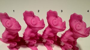
Comparison of 4 different layer heights (finest to roughest from left to right)

Infill- How dense the object printed will be, ranging from completely hollow(0 %) to completely solid (100%). Note that as you get higher and higher in percentages, the difference starts to become less noticeable. The shape of the infill is usually also adjustable, these include hexagonal, rectilinear, or even custom settings.
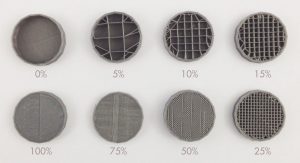
Examples of different infill percentages
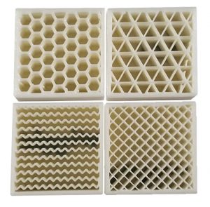
Different infill types

Shells/Perimeter- The number of outer lines the printer will produce on the perimeter of the print. The standard is two. This affects the strength of the print.

Speed- How fast the print nozzle will move during the printing process. Higher speeds give faster prints, but lower quality, while the reverse is for lower speeds.

Supports- If your print has overhangs, depending on the angle, the printer may attempt to build the layers over nothing, causing a drooping effect. To compensate, supports (layers thinner than usual), are created by the printer which can be broken off or in some cases dissolved later. The density of the supports can usually be adjusted as well. Flimsy supports break away easily, but may also be torn away accidentally by the extruder during printing, while more rigid supports are can hold more reliably but are harder to remove.
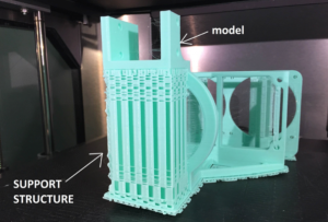
A model with support material

Raft/Skirt/Brim- The more surface contact that your print has, the better it will adhere to the printed during printing. If it has little surface area, there is a possibility that it will actually peel off the printer. In these cases you may want to use a raft, skirt, or brim. There are all similar but each has a specific use. The raft is the most generic and is like support structure but is only composed of a few layers that the model is printed on top of. It is used to provide a larger “footprint” for the model and is removed like support material. Take note however, that the bottom of the print is usually affected by this, as it will tend to be more rough having been printed on top of more material rather than the print bed. A skirt is like and outline of the print made around it. This is to ensure that the filament is flowing properly before the actual print begins. A brim is like a raft, except the bottom layer is printed with the brim instead of on top of it. It provides stability to prints with small contact points, and can be removed or kept on after printing. More info on all of these here https://www.simplify3d.com/support/articles/rafts-skirts-and-brims/

Temperature- Both the temperature of the extruder and the buildplate of the printer can be adjusted in most slicers. The temperature of the extruder and bed should be adjusted depending on the type of filament that you are using. Most filaments come with a suggested nozzle and build plate temperature. Sometimes, the bed may not even need to be heated. Printers also come with fans for the purpose of cooling the components and/or the filament itself. Slowing down or speeding up the fans will affect the flow rate of the filament as well as the quality of the print. This usually doesn’t need to be adjusted but feel free to experiment.
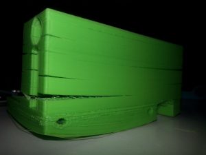
Warped bottom and split layers due to poor adhesion and/or temperature settings
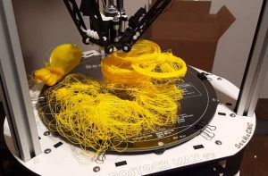
If you need a heated bed make sure it stays on

Retraction Rate- Since the filament in the extruder is under constant heat, it will always want to flow out of the extruder. As the nozzle moves about, small bits of filament may be extruded unintentionally. The retraction setting allows the filament to be withdrawn back to prevent this from happening. Too little a retraction rate will cause strings, while too great may actually wind the filament out of the extruder. Once again, a setting that may some testing to find what works best, it also depends on the filament used as well as the temperature.
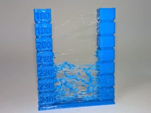
An example of too low a retraction rate

There are more settings than those listed, but these are usually the ones that affect print quality the most. Another factor that can affect prints is random bugs in software or issues in the actual model that affect slicing. This is why you should always review your model after it has been sliced in your slicer software before uploading it to the printer. Some slicers have their own file repair settings, but online repair services can be good as well. https://makeprintable.com  https://tools3d.azurewebsites.net
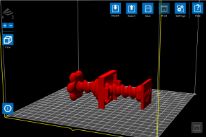
File loaded into software before slicing
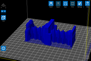
Sliced file output, note the large block in the center of the model that was not present in the original

3. Hardware

3D printers, like all machines, can and will eventually fail and usually require maintenance. You don’t necessarily have to take your printer apart bit by bit, but you definitely need to check on your printer and its components every now and then to ensure every things is fully functional. If desired, you can also upgrade your printer parts with purchasable upgrades, or even print add-ons that will improve print quality.

Extruder- The integral part of the printer responsible for the actual printing. A user needs to make certain that this piece is fully functional and taken care of, otherwise no printing can occur. Taking care of your extruder is relatively simple. Just make sure that it is not overworked and kept clean. Prints that run for hours are fine, but you definitely you should not have your printer running 24/7. After a long print maybe give it a break for a few hours or so. Make sure to exercise proper fan usage. It is wise to have at least one, if not even 2 fans running on the extruder during prints. This improves print quality and extends the lifetime of the component. Also, whenever possible make sure to allow your fan to cool off your extruder instead of just turning the printer off. By allowing the fans to run after a print, the extruder can cool properly and gradually unit the next print. Overheating can cause filament to stop flowing entirely and damage the extruder, so be wary of this. It is also a good idea to maybe open up your extruder whenever you see an issue in printing or just feel like it’s time to clean it. When attempting cleaning, a wire brush is usually the go-to tool as most if not all extruder nozzles are made of metals like brass.
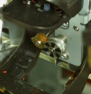
Bits of filament stuck in the drive gears of the extruder can really cause printing problems
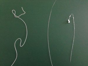
Signs of extruder problems. The left filament strand is fine, while the center is too thin and the rightmost is too “globby”
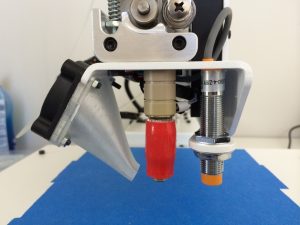
A 3D-printed fan mount made by the printer for itself to improve quality

Build plate- Maintaining the integrity of the build platform is key to ensuring good prints. While they can be fixed/replaced like extruders, they are usually much more difficult to do so. One of the most important aspects to look out for is leveling, as in keeping a proper distance between the extruder nozzle and the build surface. Too far and the filament will not stick; too close and the filament will have no room to exit the nozzle and the bed may be damaged. Most printers come with instructions on how to properly level the bed, and some even have auto-leveling settings. Manual offsets can also be input if desired. Like the extruder, it is important to keep the bed clean, as residue from prints and glue for adhesion if used, can buildup overtime and harm the surface as well as your prints. One method of preventing this is using painter’s tape. By applying it over the build plate, you can provide a surface that in some cases is actually better for adhesion than the actual platform, as well as easily peel off the prints afterwards. It also assists in protecting the bed. Many printers also come with beds made from glass, which must be taken care of with caution, as overheating or mishandling of the printer can damage the bed severely and become a safety hazard.
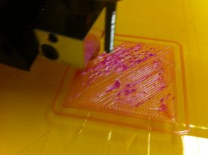
Sign that the bed is adjusted too close to the extruder
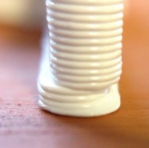
A print with an offset shift due to a loose build plate
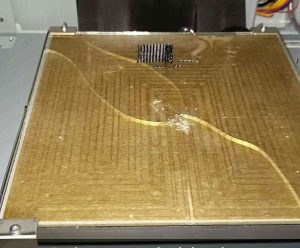
Chipped and cracked glass bed, most likely occurred when trying to remove a print

Motors- In order to drive the axes of the printer’s nozzle and bed, stepper motors are used. One motor is used for each axis(X, Y, and Z), and the extruder and bed can either share all three, or one may posses all of them (in which case that respective part would be the only one moving). These motors are what allow 3D printing to be 3D. Most use tension belts or rods to move the extruder and/or bed. This motors don’t require as much maintenance and checking as the nozzle or bed, but it is certainly a good idea to check on them and perhaps regrease them every now and then. You may also want to check the wiring on the motors, as the repeated motion of moving back and forth can actually break them and sometimes even get caught in the gears, effectively ruining the printer. Unless you’re experienced in electronics, this can be difficult to fix. Taking good care of your motors can not only save you from buying new ones later, but also improve print quality. Everyone can agree that the smoother a print is, the better it looks and the higher quality it is. The accuracy of the prints depend on the stability of the motors. If they are too tight or too loose, your prints will suffer.

A stepper motor with a loosened belt

A print with ridging along the z-axis, a sign of wobbling motors
Time for Action

It was finally time to put our CADing, ideation and prototyping skills into action. Our group, JJJ inc, is designing a smart switch which can potentially pave way for cheaper smart homes and user customization. We started the class with watching a few videos on getting our spirits up and running. Before class our team had the general design concept in mind, in which we wanted to install a box on top of a light switch and have a motor move it up and down remotely, but we had not thought about the constraints of the functionality and in the design itself.

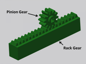
We then headed to the CU Fab lab to explore and get advise about our design and its functionality. One of the helpers at the fab lab suggested we use a rack and pinion arrangement to move our switch up and down. We then designed and discussed our idea among the team and came up with a simple working model which could be simply 3-D Printed. Our idea is to attach a motor to the Pinion Gear which is connected to a rack gear which moves linearly. The rack gear will have a hole in its center which will be mounted over the light switch.

Our next step was to CAD the rack and pinion using Fusion 360. We started of with first measuring the dimensions of the light switch to get an idea about how much the rack must move linearly to push the switch into position. We then used it to design the rack and pinion model which we now have put to print.

The next step of our creation is to design a housing for the rack and pinion and to integrate a Bluetooth module using an arduino uno. Later that week I spoke to one of my friends in the ECE department who suggested that the simplest way of operating a motor remotely will be using a Bluetooth HC/05-06 module which is available readily. I can already seeing our project come to life its just a matter of a few weeks!

This a step by step guide to anyone interested in working with Bluetooth modules on an Arduino Uno board : http://www.instructables.com/id/Arduino-Control-DC-Motor-via-Bluetooth/

Soldering & Putting Together The Light Box

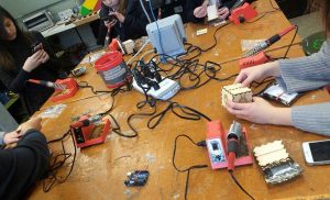
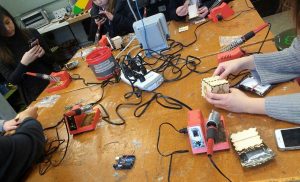
Wires are wrapped together and dangle like gruesome tentacles. A foul smoke rises in the air as the iron touches the metal. Silvery blobs form between two pieces of metal. The process of soldering is underway in the laboratory.

The third and final workshop at the Fab Lab was learning how to solder. I had no prior experience to soldering before, so I was extremely interested. The process of soldering is joining multiple pieces of metals together by melting and adding a filler metal. This results in a permanent connection between electronic components.

Looking back the process was fairly simply. We had to connect all our materials together using a soldering iron. A LED would be connected to a resistor, which would then be connected to a wire. The main concern was using knowing how to safely handle the soldering iron.

The three main safety procedures were to place the soldering iron back into its holder when finished and to never pass the iron to another person, the second was to not breathe in the gas being released when joining metals together, and to wash our hands afterwards since the materials contained lead.

During the workshop, I had difficulty getting the two pieces of metal to stay connected. In addition the metal wires were hard to twist together since they were small. I was one of the last to finish after carefully soldering all the wires together to create an octopus-shaped creature.

Once the soldering was finished, we tested them on our Arduino boards to see if the LEDs worked properly. Taking my time soldering had paid off as mines did not run into too many issues.

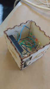
I laid out all of the components for my box on the table and began putting everything together. We had to make sure the wires were not touching one another and that the battery component was sticking out of the backside of the box. A couple drops of hot glue and a few burns later, the Arduino Light Box had been completed!

Instructables provides an easy to follow guide on soldering that can be used to apply these skills for your own project along with other projects that can help you practice your skills. Additional resources include a comic of soldering guidelines by the NASA standard.

Week 7 Summary: Building on Our Skills in the Fab Lab

In Week 7 of the Digital Making Course, our community of Makers once again ventured over to the Champaign-Urbana Community Fab Lab. Similar to week 6, our class broke into our three groups to work on the next rotation in making the Blinker Boxes. However, since we were already familiar with the layout of the building and the resources available to us at the Fab Lab, we were able to hit the ground running. Once again, our three groups were split up to working on Coding with the breadboard and Arduino, soldering the electronics, or designing the press-fit boxes for laser engraving and cutting.

Our time in the CUC Fab Lab serves many purposes. First and foremost, it provides us the opportunity to practice skills that can help us with our own making endeavors. It is especially helpful for our project groups to develop a diversified skill set that we can utilize on our semester projects. The workshops at the Fab Lab also familiarize us with the technologies and physical tools available to us. Learning from the staff also helps us get a feel for the greater Maker Community and hearing about their personal projects helped us understand their skill sets and how each of them may be able to help with our projects. Finally, spending time in our own Maker Lab, the Fab Lab, and with all the staff and volunteers gives us a better idea of the Maker Movement that is revolutionizing businesses across the nation and around the world.

Supra

Team Supra’s Concept

As we keep going through the semester, we are rapidly approaching the design and prototyping phases of our semester projects. All of the project teams are refining their “How can we” statements while defining the actual problem they are looking to solve. Our first project idea submission was due on Wednesday of Week 7. To give you an idea on some of the concepts the class is working on, Team IJK is trying to help college students decrease stress by using indoor gardening. Team XNihilo is attempting to have busy professionals or college students drink more water. The MakerLAX is hoping to “help teenagers, young adults, and anyone else who struggles” tie a tie properly. Team Zerott is trying to improve patient satisfaction at hospitals. In Week 8, the project groups will be moving forward based on the feedback they have received. Once again we will be submitting our “How can we” statements, but this time we will include a concept details, key components of the solution, the capabilities of team members, outside resources for skills and fabrication tools, and any information resources identified.

Odelia Code

Odelia spent this week in the computer section of the Fab Lab code the Arduino for the Blinker Box. Odelia said, “This was my first time actually seeing a computer board up close and I was definitely quite surprised by how it looked. Personally, I thought that it seemed quite fragile and easily breakable. However, it was quite sturdy and it could hold quite a bit of force. Along with the Arduino board, the following things were included.” After setting up the circuit and trying to adjust the code, she found working with the light sensor was the most difficult part of the lesson. I think many would agree, as the range of values corresponding to which LED flashed depended on the specific sensor and how bright the part of the lab you were sitting in was.

Chase Soldering

Chase spent the class time in the electronics section of the lab soldering his LED’s together. Reflecting on the class , said “the instructional course ultimately proved to be very time consuming and required incredible delicacy, there is little doubt in my mind that this is a crucial tool in any maker’s arsenal of building tools.” For many in the class, this was their first experience with soldering. However, we all were able to pick up on tips and tricks such as using the “helping hands” or tape to hold wires down while soldering multiple pieces together. By the end of class, Chase and his group mates were able to wire the LED’s and sensor into the Arduino he programmed in Week 6 and the LED’s flashed as planned! Finishing off his post, Chase, like many, said he hopes to “incorporate soldering in some capacity” into the final project.

Kenny Design

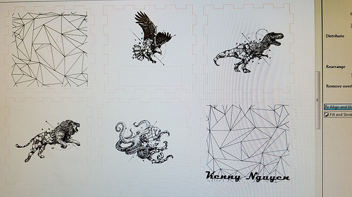
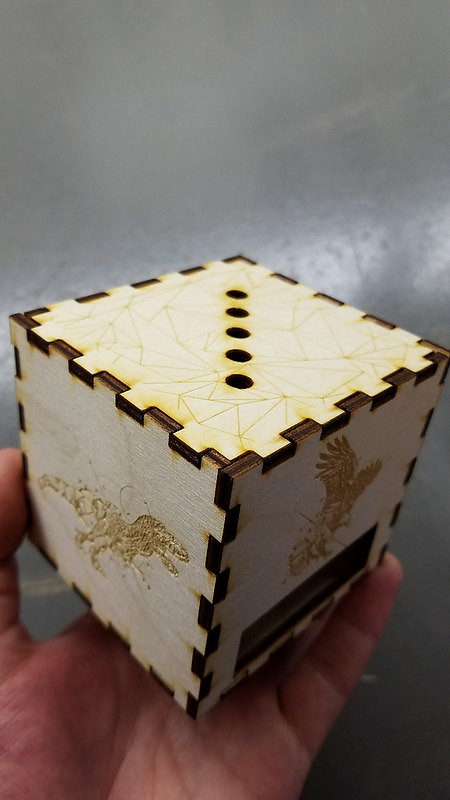
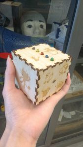
The final phase of the Blinker Box is the making the press fit box. Kenny wrote about using the free Inkscape software to design his box. By taking images from the Internet and vectoring them using the Trace tool, the images became compatible with the laser. Kenny chose artwork from one of his favorite designers to put onto his box. Once it was finished, he said, “It was very rewarding to be able to see something you design on a computer come to life in a matter of minutes. There was something satisfying from watching it go back and for until your vision comes true.”

Kenny Box

All of our blinker boxes are coming together as we build on our skills at the Fab Lab. Week 8 will be the last class session in the Fab Lab but many of us will be back to work on our projects. Happy Making!


Final Week in the Fab Lab: Coding with Arduinos

This week we faced the cold and snow as we headed to the Fab Lab for our final session of our 3-week long workshop at the Fab Lab. After working in the electronics area to solder, the laser area to make the press-fit box housing, it was time to work in the coding area at the front of the Fab Lab.

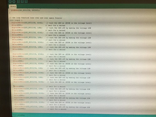
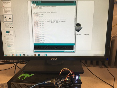
Assisting our group with the Arduino portion were Fab Lab staff members Andrea Vozar and Alexis Papak. After an introduction to the interface we would be using to practice our coding, we started taking out all the components in our kits. To familiarize ourselves with the basics, we set up a simple circuit and opened up some example code that would cause an LED to flash on and off. We were than challenged to change the code so that it signaled the SOS message Morse code. After adding a few lines and changing some values then uploading the new code to the Arduino, I was able to successfully make the LED signal SOS. Then we were challenged to add a second LED and code it so that the lights alternated flashing. After changing the existing code and adding more lines to accommodate two separate LED’s, the lights alternated flashing.

IMG_1137

Once we were comfortable with our introduction to coding, it was time to start working on the Blinker Box. We followed a schematic to assemble our soldered LEDs into the right pins, ground, and power source. Then well pulled up the coding for the light box and uploaded it to the Arduino. Now we had to test the photo resister to determine the range of light intensity that was being sensed. After a few attempts of trial and error, I was able to identify an appropriate range for the LED’s to light up at and eventually cycle through flashing. Finally it was time to assemble the box. Using the press-fit cutouts from last week, I put the LED’s and photo resister through their respective holes, and then assembled the box around the Arduino. After 3 weeks of hard work, the project was completed!

IMG_1138

Over the past three weeks, working at the Fab Lab provided a solid foundation of 3 different areas of making. Not only do we have a tangible object to show off our learning, we are also comfortable working in the fab lab and can now use what we learned on our group projects and hopefully our own personal projects. To help with personal or the group project, I found Hackster.io, an online community geared towards helping people learn about hardware. You can search difference projects by proficiency level, application type, hardware unit, or many other options. it reminds me of Thingiverse in that you can search and use product categories as well as the community platform it provides.  For the group that is considering Hydroponics product, I found this project using Arduino and Raspberry Pi, which may be helpful.  The Arduino website also has a great collection of resources for learning the various Arduino products, programming, and offers several tutorials to work through.  Happy Making!

Week 6: First Visit to the Fab Lab

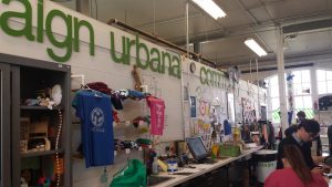
This week, we paid a visit to the surprisingly out-in-the-open Champaign-Urbana Community Fab Lab; a free community center-like makerspace open for anyone. The Fab Lab is aptly named as the inner workings of the building are almost like a laboratory filled with fabulous creations by the volunteers and others who happen to stop by. Unlike our Digital Making Lab, it contains not only 3D printers, but other varieties of technology designed for the specific purpose of creation. These include sewing machines, paper cutters, laser engravers, and soldering stations. The lab contains a plethora of methods for people to express their creativity; it’s a shame that it is not very well known.  < Outside view of the Fab Lab

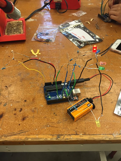
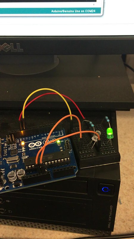
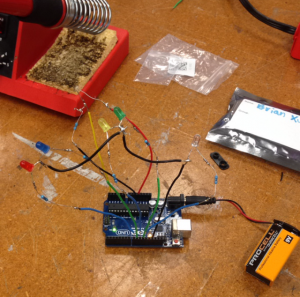
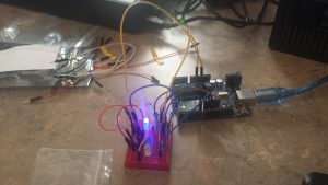
For the first week here in our 3 part saga in this lab, one person from each of our groups was assigned to a station in the lab where we would participate in a different workshop to make something out of nothing. For my personal station, we worked in electronics. I chose this because as an electrical engineering major it was definitely in my all you expertise and I knew that I would be able to learn something to improve upon. Our project was creating a type of light-sensing electronic circuit using LEDs, a photocell resistor, and an Arduino. Depending on the amount of light sensed by the resistor, a different color LED would light up. If no light was sensed, then all the LEDs would turn on. The project involved looking at some schematics and quite a bit of soldering, and the end result as it currently stands (an Arduino board with a bunch of wires and LEDs branching everywhere) did not look so appealing, but the functionality was the true beauty of it. Plus, we should be able to improve upon and make the design “prettier” in our next workshop. The other two groups were split into those working with laser cutters and coding in the computer lab portion of the Fab Lab. Laser cutting is another type of 3D printing in a sense, but in a way opposite to the norm. Instead of starting with nothing, your starting material is already there. You just need to decide upon a design and what portions you wish to cut out rather than add on. The results are stunningly precise. And while coding might not seem as glamorous as the other two activities, it is the basis of modern day electronics. Virtually every device for use by citizens requires some programming: phones, computers, televisions, and the 3D printers we use in our lab. It may not inherently make some visually stunning object, but without it we wouldn’t be able to use the machines that make those objects in the first place. All in all, these activities were extremely enjoyable to spectate and participate in, and in doing so we’ve gained knowledge of more methods for our use in not just our final project, but Making as a whole.

 Arduino Circuit

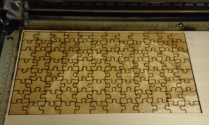
Laser Cut Tiger Puzzle


Learning and Making

Week 6 was all about learning and making at the Champaign Urbana Community Fab lab. The Fab Lab does a tremendous job in inspiring interest and innovation among the members of the community. As I walked into the Fab lab, I was amazed to see how many different machines and materials they had for us to create almost anything we imagined. Jeff Gringer who is the Director of the Fab Lab even told us that the building was the second oldest on campus and it once had huge doors to let horse carts in!  I was particularly excited for this class as I was looking forward to learn how to use Arduinos and apply them to my teams final Project. After a brief introduction of the MakerSpace, our team was split up into 3 groups with each group working on a different skill. I was put into the team which had to design an Arduino circuit which detected light and powered LED’s based on the ambient light in the room. 2 Volunteers working at the Fab Lab provided us with a step by step guideline on how to wire the Arduino on a breadboard. After wiring up our circuit, we connected the Arduino to a Desktop and messed around with some C code to bring our circuit up and running.

It was a great experience working with Arduinos as I never really understood its power and application value. As our teams project is geared towards making Smart Homes more affordable, I positively believe that we can use Arduinos in the product we are designing. The next two weeks our team is going to work on the final project proposal and put the theory and skills we learnt into action.

** Check out hackster.io , its like a pinterest for cool projects mostly related to Arduinois which can be shared and done by anyone. It also provides detailed instructions and materials which can be easily purchased from their website. The Motion Sensor Water Gun was something I was checking out as I was going through their website.