Team MakerLax Tie Assistant Project Reflection

Overview:

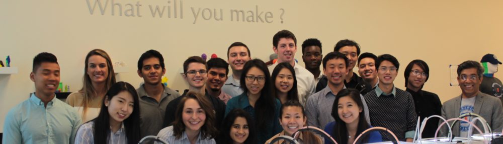
The MakerLax Team consists of three members with very diverse backgrounds. Brian is a freshman majoring in electrical engineering, Peter is a senior in advertising, and Chase is a senior in business. Having three strongly uncorrelated majors allowed us to experience a wide range of perspectives throughout the semester. While at times one of us were unfamiliar with a certain part of the making process, the others would step in and help fill the knowledge void.

Motivation:

While our initial ideas proved to be either too complex or out of the scope of this course, we ultimately decided on our final topic based on an article Vishal shared during one of our classes. The article focused on creating a “How Can We?” statement, which essentially stated that, in order for an idea to become a reality and a finished product, it must first meet three criteria. First, the idea needed to be narrow in its scope. Users should be able to understand the capabilities and capacity of the product without needing an extensive manual to guide them. Next, the idea should be local in its presence, meaning that the product should serve some type of purpose that fulfills a need in the surrounding community. By doing this, the creators will already be familiar with the problem and can devise more intuitive solutions. The final requirement for this product was that the answer needed to be realistic. Users cannot be expected to have advanced knowledge of programming, for example, in order to fully utilize it. Drawing from these three requirements, we ultimately decided to gear our making efforts towards aiding students in preparing for professional engagements, such as interviews, career fairs, or networking events.

Prototypes:

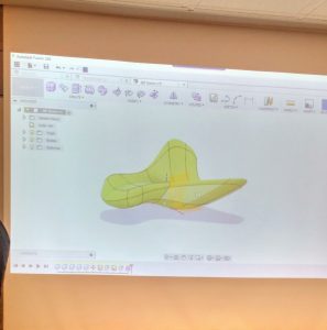
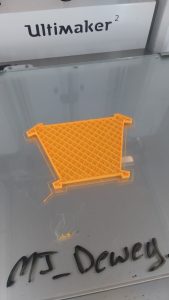
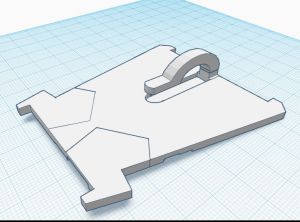
The very first crude prototypes that we created were paper models. They were quickly fashioned to act as both visuals, as well as to test different shapes for our design. After we decided on one, we recreated that form in Fusion 360. Our very first print was only meant as a test for the shape that we decided to implement. Initially, we considered making the design modular in some way. Either by adding tabs for the parts to lock into, or by creating a “puzzle piece” design. Eventually, we decided to keep the design as a single unit. Afterwards, we shifted to TinkerCAD as we believed it would better for our purposes. We then printed more models to test various clip designs. After we found a suitable one, we moved to testing. The size and shape seemed fine, but it was a bit cumbersome to wrap the tie around the sturdy print. It was this that caused us to move on to the semi-flex filament for our last design. After reprinting the last model in semi-flex and testing it, we found it satisfactory and used everything we gathered to create the final product.

Final Product:

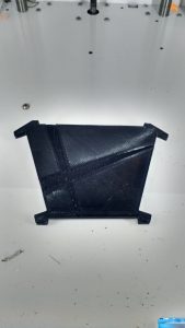
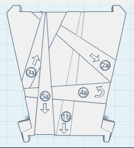
Our final product was, at first, our second to last model. After producing and testing the semi-flex model, we thought it was suitable enough to be our final design. However, somewhat last minute, we decided to improve upon it further. We decreased the dimensions, and redid the shape to make it more versatile. Physical features such as grooves and numbering were added to act as guides and “mini-instructions” to improve the ease of usage. It still is not necessarily perfect, and the print itself did not turn out that well, but it is quite an improvement on the original.

Features & Benefits:

Our final design has a thin and sleek profile, making for easy storage. It can easily fit within a pocket or portfolio. The flex material makes it very malleable and not very prone to breaking. This also allows one to utilize it with ties of varying shapes and sizes, and work it with ease. The clip is barely noticeable and and the physical structure of the design allows it to hold a tie snugly while at the same time allowing for easy removal. The indentations in the front face of the model are of different depths, allowing a user to feel around for the different steps. A number and arrow system are also engraved into the face that coincide with the instruction manual. Aside from allowing one to tie a tie around oneself, it can also be used to store a premade tie, in the event that the user foresees a circumstance for it.

User Feedback:

Overall, we found user feedback to be incredibly helpful during our prototyping phase. We had both in class feedback along with feedback from students outside the classroom. During the sessions, we were able to observe how our products were used the and difficulties that occurred. One student said, “I suggest adding instructions or some kind of step-by-step process to make using the product easier.” We took their advice and created a pamphlet as part of the packaging and adjusted the clip size and indents on our original prototype.

Future Improvements

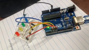
We hope to utilize more materials in future prototypes. Semi-flex filament was different to handle and took the 3D printers multiple tries to print out our prototype, so we hope to test different types of semi-flexible materials. One feature would be to have a collapsible, modular format. The benefit would is that the user can easily remove the product once they had completed tying their tie. From the user feedback, the other suggestion we were given was to incorporate electronics into our design. The product would have an LED guidance where different sections would light up green to guide the user to tie the tie. The LED guidance would require coding and implementing a small arduino and a battery into the product.  

Takeaways:

After the conclusion of this project, our team came away with three main conclusions from the experience. Firstly, it was incredibly satisfying to see our weeks of efforts and labor culminate in a working and usable model. One of our team members who previously was unfamiliar with how to tie a tie was able to learn how, with the guidance of our product. After seeing it be put to use, we can say with complete certainty that our efforts proved worth it. Additionally, we learned that rapid prototyping is critical to the making process, and to creating an effective final product. We spent the majority of our initial efforts attempting to make the perfect first prototype, when in reality the majority of our progress came upon the third and fourth iterations. Similarly, our team realized the immense importance of receiving user feedback. While we had certain connotations of the direction we wanted to pursue with our product, obtaining feedback from users that were unfamiliar with the making process gave us great insight as to what the average user would actually prefer.

Slide Presentation:

https://docs.google.com/presentation/d/1IPbJ5ryCkPmgwZ3aqKYncMZNeR6uIaXsuPVW9Mw8MWc/pub?start=false&loop=false&delayms=3000

Looking Back

Looking back at this semester and thinking about everything that I have learned is incredible. This class has introduced me to things I was unfamiliar with. It gave me the skills to be able to go about an idea in serveral different ways.

I thought back to some of the speakers that made an impact on what I learned. Even on the first week, when we had two speakers. The video call from John Horlick kicked off the semester. He had written a book on how 3D printing was really becoming more and more prevalent in business and our everyday life. This opened my eyes to Digital Making. I realized that things were constantly changing in how things were being made, but I did not realize how much of an impact innovation was actually making. Even though this presentation was mainly on 3D printing, I felt like it spoke for more than 3D printing. It showed that there is always a better or smarter way to do something. There are also many ways to achieve that goal and I believe that is what Digital Making entailed.

Most of everything I learned in this class, I had not been exposed to before. Something that was really foreign to me was coding aurduinos. I never thought I would mess with that. I had understood some of the code because I had dealt with coding before, but it had only been solely on the computer. I had never used a breadboard before. It was also awesome to see a product come together after our few weeks of class spent at the Fab Lab. Not only did we code Arduinos, but we lasercut wood boxes and soldered wires together. This was great experience that helped prepare us and our teams create and develop a product of our own for our final product.

Throughout the entire semester, I felt like each class taught us the skills to tackle a problem or accomplish a task that we would encounter as we did our final project. The guidelines of the final project were for you to create a project that solves a problem.

When I decided to take this class, I was hoping to get a better understanding of using different softwares. I took this class because I really liked the work I did in the lab and I wanted to be able to do more. I only had one class freshman year that I was taught a CAD software, Creo Parametric 3.0. Other than that, the only time I have had experience with other softwares was when I would help out with workshops at the MakerLab. I wanted to be able to learn them well enough to create things of my own.

I feel like that expectation I had about the class was met. I was taught various softwares through a workshop type environment in class. That helped with figuring out where to start and what to look at to finish a design. Then I had to apply those skills I learned to the final project. It really tested me on how well I knew how to use them. I used Tinkercad for most of anything I did with the final project including the team logo. I was able to do it from my laptop in my free time. When I was looking at a folder I created on TInkercad and photos of designs I had sent my partners, I could see how my skill had improved throughout the semester. When I started, I did the basic shapes and a lot of things were uneven and had odd proportions. As I practiced, I was able to fix those problems and create more complex things. It was frustrating at points, but I was able to get my designs to how I wanted them to be.

This class opened my eyes to many things.  I was able to explore different ways of making I had never done before. I also, went through the product design process that made me explore every aspect of a design even if it is identifying what you can do yourself and when to seek outside help. In this class, I learned what I wanted to learn and more.

Product Testing

We are at a time in the semester where everything is coming to an end. This is also a time where everything on our product is coming together. Throughout the semester we have developed a product through rapid prototyping. Now we have reached the point of product testing. This will help teams figure out what they need to fix to either make their product better or appeal to more consumers.

It has been a journey for my team to get to where we are now. Last week, we had a small prototype of our product. It was functional. As we held it in our hands, we realized what we could improve. We thought we needed a bar at the front of the device to keep it from letting the sliding mechanism from sliding out. We also thought the sliding mechanism could be longer. Besides the improvements we were able to notice as a group, we met with other groups to get their feedback. This was very helpful to get their feedback. Since others teams are going through the same process of developing a product, they have helpful insight. One team told us that they felt some of the sides need to be made thicker. If we increase the sides then we are less likely to have weak points in our design. Other than those comments, the teams liked our design and that we were going to use the Flex material to the sliding mechanism.

After getting that feedback, my team and I went to work on making changes to our design. We essentially made everything thicker. We also added a bar to the edge of the base. This is to prevent the sliding mechanism from sliding off. In order to make this adjustment we had to make the sliding mechanism into 2 parts. The handle on the sliding mechanism is separate from the entire mechanism. We will just need to glue those two parts together. I thought this would be fine because the handle does not need to be very strong since it does not come into direct contact with the door.

These adjustments got us closer to our final design. Although since we did make more adjustments, it did set us back on properly testing our product. We should be able to put our print on again to have it printed in the flex material. Then we will be able to do proper testing!

Seeking Advice

Last week, my team and I still had a lot to decide. After the previous week of completely changing our product idea, we had a lot of ground to make up. We were basically starting from scratch. We still did not have a clear product idea and wanted advice on where to go. So our goal by the end of class on Monday was to make a plan. We decided on a design. Our design was to have on piece that had a notched design attached to the door. Then we would have a moveable part that moved in the notched part to slide out to ajar the door and slide back in when you would want to door to close. We were unsure on what materials to choose, but we were thinking of using thick metal and coving it in a rubber resin.

The next day we went over to the Fab Lab seeking advice. When we got there we showed them our plan. We went back and forth on what would work and what would not work. We decided that using metal was not the way to go. It in the end would be very expensive and we would probably have more luck with either wood or plastic. The problem we might have with wood is that we might put out more effort and time than necessary. They suggested that we us CAD software to try different variations and we could always print it and see how or design works. Going to the Fab Lab was very helpful because we had a better idea of where to go with our design!

Now we have to figure out exactly what we are going to do. We have thought of two designs so far that we have run through this past week. One design was like the original slide out the side of the door. Another design we had was to have something we could slide a bendable material to ajar the door from the top. These ideas are similar, but go about ajaring the door from different sides of the door. Currently we have not decided on which design we will choose, but hopefully by class on Monday we have made that decision. I think it is better that we have thought of different options to go about solving our problem instead and drawing a blank. This is a process we are consistently going through.

How to get “Perfect” Prints

One of the best features of consumer 3D printers is their ease of use. All the user needs is to slice their model with their desired settings and upload it to the printer via a USB cable, flash drive, etc. While this is straightforward, there are quite a few intricacies to the process. Slicing a 3D model with “perfect” settings does not necessarily lead to a perfect print. There are a plethora of discerning factors and principles of additive manufacturing that can skew the results. These problems are usually grouped into 3 categories: material  issues, software, and hardware. User error can sometimes come into play, but that also usually falls into one of these three mentioned. 3D printing as it is now is not a perfect science, there are many issues prevalent within the technology that prevent it from being greater than what it already is. The slightest mishap during or even before a print begins can cause it to fail or lower in quality. Sometimes, prints even fail for seemingly no reason, and the failed print is simply a one-time occurrence. We can, however, take measures to ensure that we can get the best quality out of our machines as possible. As 3D printing is still rapidly evolving, there really is no “perfect” print. We can get very high quality parts created, but as it stands now there is always something that can be improved in a print. This post is meant to serve as a universal guideline/checklist for getting the best quality prints out of your 3D printer as possible.

1. Filament:

There are a variety of printing materials out there, with the 2 most popular being ABS and  PLA. Other types are special exceptions but they usually have the same conditions for printing as one of these two. You should choose what type of filament to use based on what your part requires. Each has its trade-offs.

ABS- Relatively strong with a little bit of flex. Good for parts that will be used a lot, or pieces that you don’t necessarily care how they look. However, it is NOT food-safe, and somewhat difficult to print. It requires a heated printed, and sometimes a little bit of glue on the surface to help with adhesion. It also has a very strong odor so you need a well-ventilated area.

PLA- Probably the most common material used today. It is vegetable-based and is easier to print than ABS. It also tends to look nicer and the prints are more clean coming out. However, it is much more fragile and sensitive to temperature. Therefore, this is good for models that won’t be used heavily and are more for display.

More in-depth info on filaments here: https://pinshape.com/blog/popular-3d-printing-filaments-3d-printer-filament-types/

2. Software

When slicing your file in your slicer, you have a variety of options. Different combinations produces different results, however, these can vary widely depending on the software and the printer, as well as the filament. An important consideration before printing is what kind of software you are using and if it works properly with your printer. Some companies produce their own proprietary software that can only be used with their printers and vie-verse. This makes it easier for users, but in most situations this actually limits the options. They are many other non-locked slicing softwares that can be used with any printer, but not all printers can use any software. Sometimes you will simply have to test these for yourself and see what is compatible with your printer. These are the more common options adjusted by users.

Layer Height- How tall the layers of the filament are in the z-axis(upwards direction). Usually ranges from .1 mm to .4 mm. The finer the layers, the higher quality the print will be.

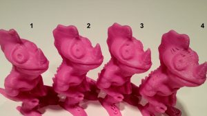
Comparison of 4 different layer heights (finest to roughest from left to right)

Infill- How dense the object printed will be, ranging from completely hollow(0 %) to completely solid (100%). Note that as you get higher and higher in percentages, the difference starts to become less noticeable. The shape of the infill is usually also adjustable, these include hexagonal, rectilinear, or even custom settings.

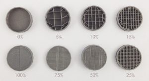
Examples of different infill percentages

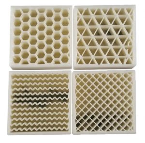
Different infill types

Shells/Perimeter- The number of outer lines the printer will produce on the perimeter of the print. The standard is two. This affects the strength of the print.

Speed- How fast the print nozzle will move during the printing process. Higher speeds give faster prints, but lower quality, while the reverse is for lower speeds.

Supports- If your print has overhangs, depending on the angle, the printer may attempt to build the layers over nothing, causing a drooping effect. To compensate, supports (layers thinner than usual), are created by the printer which can be broken off or in some cases dissolved later. The density of the supports can usually be adjusted as well. Flimsy supports break away easily, but may also be torn away accidentally by the extruder during printing, while more rigid supports are can hold more reliably but are harder to remove.

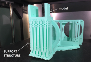
A model with support material

Raft/Skirt/Brim- The more surface contact that your print has, the better it will adhere to the printed during printing. If it has little surface area, there is a possibility that it will actually peel off the printer. In these cases you may want to use a raft, skirt, or brim. There are all similar but each has a specific use. The raft is the most generic and is like support structure but is only composed of a few layers that the model is printed on top of. It is used to provide a larger “footprint” for the model and is removed like support material. Take note however, that the bottom of the print is usually affected by this, as it will tend to be more rough having been printed on top of more material rather than the print bed. A skirt is like and outline of the print made around it. This is to ensure that the filament is flowing properly before the actual print begins. A brim is like a raft, except the bottom layer is printed with the brim instead of on top of it. It provides stability to prints with small contact points, and can be removed or kept on after printing. More info on all of these here https://www.simplify3d.com/support/articles/rafts-skirts-and-brims/

Temperature- Both the temperature of the extruder and the buildplate of the printer can be adjusted in most slicers. The temperature of the extruder and bed should be adjusted depending on the type of filament that you are using. Most filaments come with a suggested nozzle and build plate temperature. Sometimes, the bed may not even need to be heated. Printers also come with fans for the purpose of cooling the components and/or the filament itself. Slowing down or speeding up the fans will affect the flow rate of the filament as well as the quality of the print. This usually doesn’t need to be adjusted but feel free to experiment.

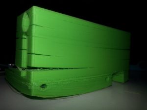
Warped bottom and split layers due to poor adhesion and/or temperature settings

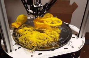
If you need a heated bed make sure it stays on

Retraction Rate- Since the filament in the extruder is under constant heat, it will always want to flow out of the extruder. As the nozzle moves about, small bits of filament may be extruded unintentionally. The retraction setting allows the filament to be withdrawn back to prevent this from happening. Too little a retraction rate will cause strings, while too great may actually wind the filament out of the extruder. Once again, a setting that may some testing to find what works best, it also depends on the filament used as well as the temperature.

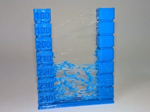
An example of too low a retraction rate

There are more settings than those listed, but these are usually the ones that affect print quality the most. Another factor that can affect prints is random bugs in software or issues in the actual model that affect slicing. This is why you should always review your model after it has been sliced in your slicer software before uploading it to the printer. Some slicers have their own file repair settings, but online repair services can be good as well. https://makeprintable.com  https://tools3d.azurewebsites.net

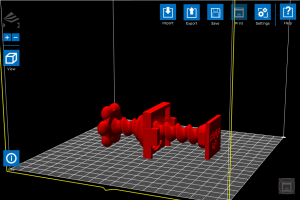
File loaded into software before slicing

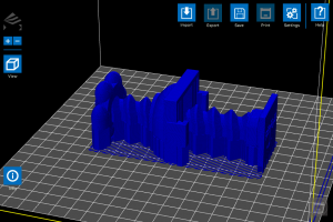
Sliced file output, note the large block in the center of the model that was not present in the original

3. Hardware

3D printers, like all machines, can and will eventually fail and usually require maintenance. You don’t necessarily have to take your printer apart bit by bit, but you definitely need to check on your printer and its components every now and then to ensure every things is fully functional. If desired, you can also upgrade your printer parts with purchasable upgrades, or even print add-ons that will improve print quality.

Extruder- The integral part of the printer responsible for the actual printing. A user needs to make certain that this piece is fully functional and taken care of, otherwise no printing can occur. Taking care of your extruder is relatively simple. Just make sure that it is not overworked and kept clean. Prints that run for hours are fine, but you definitely you should not have your printer running 24/7. After a long print maybe give it a break for a few hours or so. Make sure to exercise proper fan usage. It is wise to have at least one, if not even 2 fans running on the extruder during prints. This improves print quality and extends the lifetime of the component. Also, whenever possible make sure to allow your fan to cool off your extruder instead of just turning the printer off. By allowing the fans to run after a print, the extruder can cool properly and gradually unit the next print. Overheating can cause filament to stop flowing entirely and damage the extruder, so be wary of this. It is also a good idea to maybe open up your extruder whenever you see an issue in printing or just feel like it’s time to clean it. When attempting cleaning, a wire brush is usually the go-to tool as most if not all extruder nozzles are made of metals like brass.

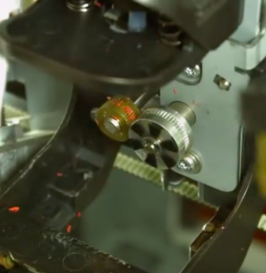
Bits of filament stuck in the drive gears of the extruder can really cause printing problems

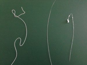
Signs of extruder problems. The left filament strand is fine, while the center is too thin and the rightmost is too “globby”

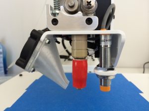
A 3D-printed fan mount made by the printer for itself to improve quality

Build plate- Maintaining the integrity of the build platform is key to ensuring good prints. While they can be fixed/replaced like extruders, they are usually much more difficult to do so. One of the most important aspects to look out for is leveling, as in keeping a proper distance between the extruder nozzle and the build surface. Too far and the filament will not stick; too close and the filament will have no room to exit the nozzle and the bed may be damaged. Most printers come with instructions on how to properly level the bed, and some even have auto-leveling settings. Manual offsets can also be input if desired. Like the extruder, it is important to keep the bed clean, as residue from prints and glue for adhesion if used, can buildup overtime and harm the surface as well as your prints. One method of preventing this is using painter’s tape. By applying it over the build plate, you can provide a surface that in some cases is actually better for adhesion than the actual platform, as well as easily peel off the prints afterwards. It also assists in protecting the bed. Many printers also come with beds made from glass, which must be taken care of with caution, as overheating or mishandling of the printer can damage the bed severely and become a safety hazard.

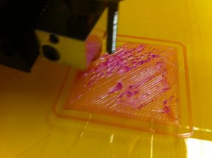
Sign that the bed is adjusted too close to the extruder

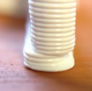
A print with an offset shift due to a loose build plate

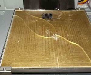
Chipped and cracked glass bed, most likely occurred when trying to remove a print

Motors- In order to drive the axes of the printer’s nozzle and bed, stepper motors are used. One motor is used for each axis(X, Y, and Z), and the extruder and bed can either share all three, or one may posses all of them (in which case that respective part would be the only one moving). These motors are what allow 3D printing to be 3D. Most use tension belts or rods to move the extruder and/or bed. This motors don’t require as much maintenance and checking as the nozzle or bed, but it is certainly a good idea to check on them and perhaps regrease them every now and then. You may also want to check the wiring on the motors, as the repeated motion of moving back and forth can actually break them and sometimes even get caught in the gears, effectively ruining the printer. Unless you’re experienced in electronics, this can be difficult to fix. Taking good care of your motors can not only save you from buying new ones later, but also improve print quality. Everyone can agree that the smoother a print is, the better it looks and the higher quality it is. The accuracy of the prints depend on the stability of the motors. If they are too tight or too loose, your prints will suffer.

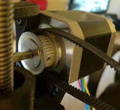
A stepper motor with a loosened belt

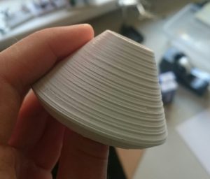
A print with ridging along the z-axis, a sign of wobbling motors

Making Adjustments

Last week team Supra went in with a trash compacting idea and have completely changed the whole idea. As we were approaching the prototyping stage of our product we had a lot to consider. Does our product solve the problem? Does it appeal to the consumer? Is it still low cost?

My team and I faced a few problems. We did not feel like our product had much of a need since we had redesigned it. So we needed to start over with our design of the trash compactor. We thought from the perspective to get maximum compaction. We modeled it after the Big Belly trash can you can see around campus. The design would have the look of the Big Belly so that you could throw trash in the top side to the trash can. Then the top would have a board with a weight attached that could be released to compact the trash in the can. Then the weight/board would be connected to a leaver arm that could crank it back to the top of the trash can. After thinking of this complex design we asked the question “Why would people actually need this in their household?” There is really no need for “maximum compaction” in a household trash can. We found ourselves overcompensating to fix some problems in our design and under compensating in some parts of our design. This created a massive problem for us. We thought it was best to revisit different product ideas.

We went back to our original idea list. One idea intrigued us. We wanted to create an improved version of a door stop. We find the conventional door stops that have already been designed faulty. They never really hold the door open and are hard to maneuver. So we plan on developing a door stop that you can attach to the door a few inches above the door handle. It will have a sliding function that will allow you to have it hold the door open when it is slid out and then slid in to allow the door to close. We are still in the beginning stage of figuring out how we are going to attach it to the door and what material we will use. I was originally thinking thinking plastic so it would be cheap, but I am afraid a hard slam might break it. So then I thought about using metal so it is more sturdy, but I think a thick rubber material might actually be the best. We still have a lot to figure out, but we are making a lot of progress!

Week 6: First Visit to the Fab Lab

This week, we paid a visit to the surprisingly out-in-the-open Champaign-Urbana Community Fab Lab; a free community center-like makerspace open for anyone. The Fab Lab is aptly named as the inner workings of the building are almost like a laboratory filled with fabulous creations by the volunteers and others who happen to stop by. Unlike our Digital Making Lab, it contains not only 3D printers, but other varieties of technology designed for the specific purpose of creation. These include sewing machines, paper cutters, laser engravers, and soldering stations. The lab contains a plethora of methods for people to express their creativity; it’s a shame that it is not very well known.  < Outside view of the Fab Lab
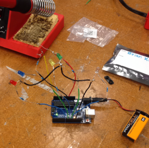
For the first week here in our 3 part saga in this lab, one person from each of our groups was assigned to a station in the lab where we would participate in a different workshop to make something out of nothing. For my personal station, we worked in electronics. I chose this because as an electrical engineering major it was definitely in my all you expertise and I knew that I would be able to learn something to improve upon. Our project was creating a type of light-sensing electronic circuit using LEDs, a photocell resistor, and an Arduino. Depending on the amount of light sensed by the resistor, a different color LED would light up. If no light was sensed, then all the LEDs would turn on. The project involved looking at some schematics and quite a bit of soldering, and the end result as it currently stands (an Arduino board with a bunch of wires and LEDs branching everywhere) did not look so appealing, but the functionality was the true beauty of it. Plus, we should be able to improve upon and make the design “prettier” in our next workshop. The other two groups were split into those working with laser cutters and coding in the computer lab portion of the Fab Lab. Laser cutting is another type of 3D printing in a sense, but in a way opposite to the norm. Instead of starting with nothing, your starting material is already there. You just need to decide upon a design and what portions you wish to cut out rather than add on. The results are stunningly precise. And while coding might not seem as glamorous as the other two activities, it is the basis of modern day electronics. Virtually every device for use by citizens requires some programming: phones, computers, televisions, and the 3D printers we use in our lab. It may not inherently make some visually stunning object, but without it we wouldn’t be able to use the machines that make those objects in the first place. All in all, these activities were extremely enjoyable to spectate and participate in, and in doing so we’ve gained knowledge of more methods for our use in not just our final project, but Making as a whole.

 Arduino Circuit

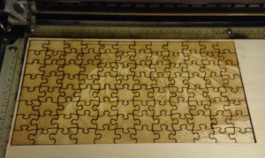
Laser Cut Tiger Puzzle


The Ideation Process

In this week’s class our group brainstormed ideas for the semester project. Our main objective during this session was identifying everyday problems that people face. We delved deeper into the process and targeted college students. At the end of the session, our group came up with three How Can We statements:

#1. How can we help young professionals tie a tie more efficiently?

#2. How can we help college students stop losing their items (phones, wallets, and keys)?

#3. How can we help young adults have more optimal audio experience?

Through these statements, we were able to think of products that could address the issues. For example, in addressing statement #2, we came up with a stopper that clips onto the bottom part of a T-shirt and the pant pocket to prevent things from falling out. As a group we decided to spend more time outside class to brainstorm ideas and coming up with more HCW statements. I think the HCW statements are a great starting point for a business idea because they are empathetic to the consumer’s needs and asks a question that can be answered in a variety of ways.

In an article from Science magazine, the authors argue that creativity is more efficient when there is a structure laid out or a framework to follow. The structure is clearly defined and may have constraints imposed. HCW statements fall under this type of creative process, since there is a sentence format to follow. Creating ideas from randomness, while still holding value, is seen as inefficient in problem-solving. I agree with the authors’ statement that creativity is “assessed by  the eyes of the beholder.” I believe both brainstorming creative ideas and coming up with an idea randomly are both effective. However, the ideas will need fine tuning as suggested in this article on evaluating business ideas.

The questions evaluate business ideas by placing them in reality. Are there enough resources? Do they address consumer needs? What are the positives and negatives of this business idea? Once you are able to answer all the questions posed, I believe your ideas will become more concrete and well defined. From this, you can set strategies for moving from the ideation phase to the prototyping phase.

There are several ways to help with the creative process. Forbes suggests individually working out and solving the problems and then meeting with your group to brainstorm. It’s important to note that brainstorming sessions can be ineffective unless certain guidelines are established. Another article from Entrepreneur suggests shying away from the need to be perfect and coming up with as many ideas, even if they’re bad. At the end of the day, I think we should try out whichever creative processes and stick with the one that work better for us.

Creating With Fusion 360 and DIY Biology

Jeffrey Smith from Autodesk held a workshop in class teaching us about the company and the Fusion 360 software. Autodesk’s Pier 9 is located in San Francisco Bay and is a facility that houses collaborations between artists, engineers, and technologists. One of their latest projects is a 3D-printed model of downtown San Francisco.

During the workshop session, we learned about the different tools on Fusion 360. I found the workshop to be incredibly helpful since I have never used Fusion 360 previously. Using the software, I tried creating a pipe that connected with a rectangular body. Other tools we experimented with were the sketch, modify, and assemble functions. Saving the best for last, we learned about the purple create tool. The tool allows us to deal with multiple faces and build complex, organic shapes. Jeffrey Smith create an aircraft design out of a rounded cube in a matter of minutes. I definitely want to practice using Fusion 360 more and utilize it in semester projects.

Dorothy Silverman presented on Biohacking, which manipulates the genes of organisms to usually create a product. Biohacking can also be thought of as DIY biology, where people of all backgrounds work together in small labs. Projects worth mentioning include using chitin to create biodegradable cups and plates and using fungi spores to grow furniture. I believe that the Biohacking movement is similar to the Maker Movement in that all sorts of people work together to create; however, Biohacking incorporates more sustainability in creating their products.

Merging Biohacking and fashion together, Suzanne Lee created BioCouture, a process in which clothes are grown using microbes. Biohacking is an exciting way to learn about biology and create things at the same time. I definitely want to experiment with the various processes involved to create sustainable products.