Team MakerLax Tie Assistant Project Reflection

Overview:

The MakerLax Team consists of three members with very diverse backgrounds. Brian is a freshman majoring in electrical engineering, Peter is a senior in advertising, and Chase is a senior in business. Having three strongly uncorrelated majors allowed us to experience a wide range of perspectives throughout the semester. While at times one of us were unfamiliar with a certain part of the making process, the others would step in and help fill the knowledge void.

Motivation:

While our initial ideas proved to be either too complex or out of the scope of this course, we ultimately decided on our final topic based on an article Vishal shared during one of our classes. The article focused on creating a “How Can We?” statement, which essentially stated that, in order for an idea to become a reality and a finished product, it must first meet three criteria. First, the idea needed to be narrow in its scope. Users should be able to understand the capabilities and capacity of the product without needing an extensive manual to guide them. Next, the idea should be local in its presence, meaning that the product should serve some type of purpose that fulfills a need in the surrounding community. By doing this, the creators will already be familiar with the problem and can devise more intuitive solutions. The final requirement for this product was that the answer needed to be realistic. Users cannot be expected to have advanced knowledge of programming, for example, in order to fully utilize it. Drawing from these three requirements, we ultimately decided to gear our making efforts towards aiding students in preparing for professional engagements, such as interviews, career fairs, or networking events.

Prototypes:

The very first crude prototypes that we created were paper models. They were quickly fashioned to act as both visuals, as well as to test different shapes for our design. After we decided on one, we recreated that form in Fusion 360. Our very first print was only meant as a test for the shape that we decided to implement. Initially, we considered making the design modular in some way. Either by adding tabs for the parts to lock into, or by creating a “puzzle piece” design. Eventually, we decided to keep the design as a single unit. Afterwards, we shifted to TinkerCAD as we believed it would better for our purposes. We then printed more models to test various clip designs. After we found a suitable one, we moved to testing. The size and shape seemed fine, but it was a bit cumbersome to wrap the tie around the sturdy print. It was this that caused us to move on to the semi-flex filament for our last design. After reprinting the last model in semi-flex and testing it, we found it satisfactory and used everything we gathered to create the final product.
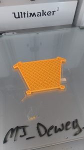
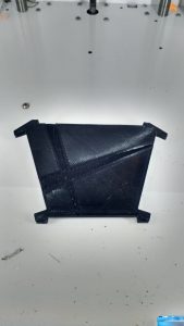
Final Product:

Our final product was, at first, our second to last model. After producing and testing the semi-flex model, we thought it was suitable enough to be our final design. However, somewhat last minute, we decided to improve upon it further. We decreased the dimensions, and redid the shape to make it more versatile. Physical features such as grooves and numbering were added to act as guides and “mini-instructions” to improve the ease of usage. It still is not necessarily perfect, and the print itself did not turn out that well, but it is quite an improvement on the original.
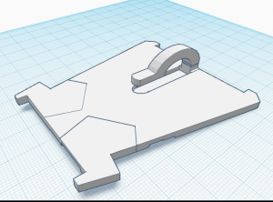
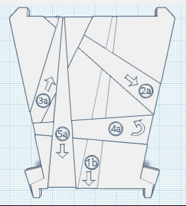
Features & Benefits:

Our final design has a thin and sleek profile, making for easy storage. It can easily fit within a pocket or portfolio. The flex material makes it very malleable and not very prone to breaking. This also allows one to utilize it with ties of varying shapes and sizes, and work it with ease. The clip is barely noticeable and and the physical structure of the design allows it to hold a tie snugly while at the same time allowing for easy removal. The indentations in the front face of the model are of different depths, allowing a user to feel around for the different steps. A number and arrow system are also engraved into the face that coincide with the instruction manual. Aside from allowing one to tie a tie around oneself, it can also be used to store a premade tie, in the event that the user foresees a circumstance for it.

User Feedback:

Overall, we found user feedback to be incredibly helpful during our prototyping phase. We had both in class feedback along with feedback from students outside the classroom. During the sessions, we were able to observe how our products were used the and difficulties that occurred. One student said, “I suggest adding instructions or some kind of step-by-step process to make using the product easier.” We took their advice and created a pamphlet as part of the packaging and adjusted the clip size and indents on our original prototype.

Future Improvements

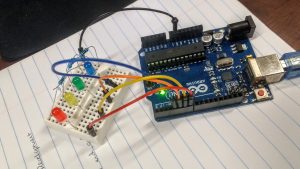
We hope to utilize more materials in future prototypes. Semi-flex filament was different to handle and took the 3D printers multiple tries to print out our prototype, so we hope to test different types of semi-flexible materials. One feature would be to have a collapsible, modular format. The benefit would is that the user can easily remove the product once they had completed tying their tie. From the user feedback, the other suggestion we were given was to incorporate electronics into our design. The product would have an LED guidance where different sections would light up green to guide the user to tie the tie. The LED guidance would require coding and implementing a small arduino and a battery into the product.  
Takeaways:

After the conclusion of this project, our team came away with three main conclusions from the experience. Firstly, it was incredibly satisfying to see our weeks of efforts and labor culminate in a working and usable model. One of our team members who previously was unfamiliar with how to tie a tie was able to learn how, with the guidance of our product. After seeing it be put to use, we can say with complete certainty that our efforts proved worth it. Additionally, we learned that rapid prototyping is critical to the making process, and to creating an effective final product. We spent the majority of our initial efforts attempting to make the perfect first prototype, when in reality the majority of our progress came upon the third and fourth iterations. Similarly, our team realized the immense importance of receiving user feedback. While we had certain connotations of the direction we wanted to pursue with our product, obtaining feedback from users that were unfamiliar with the making process gave us great insight as to what the average user would actually prefer.

Slide Presentation:

https://docs.google.com/presentation/d/1IPbJ5ryCkPmgwZ3aqKYncMZNeR6uIaXsuPVW9Mw8MWc/pub?start=false&loop=false&delayms=3000

Looking Back

Looking back at this semester and thinking about everything that I have learned is incredible. This class has introduced me to things I was unfamiliar with. It gave me the skills to be able to go about an idea in serveral different ways.

I thought back to some of the speakers that made an impact on what I learned. Even on the first week, when we had two speakers. The video call from John Horlick kicked off the semester. He had written a book on how 3D printing was really becoming more and more prevalent in business and our everyday life. This opened my eyes to Digital Making. I realized that things were constantly changing in how things were being made, but I did not realize how much of an impact innovation was actually making. Even though this presentation was mainly on 3D printing, I felt like it spoke for more than 3D printing. It showed that there is always a better or smarter way to do something. There are also many ways to achieve that goal and I believe that is what Digital Making entailed.

Most of everything I learned in this class, I had not been exposed to before. Something that was really foreign to me was coding aurduinos. I never thought I would mess with that. I had understood some of the code because I had dealt with coding before, but it had only been solely on the computer. I had never used a breadboard before. It was also awesome to see a product come together after our few weeks of class spent at the Fab Lab. Not only did we code Arduinos, but we lasercut wood boxes and soldered wires together. This was great experience that helped prepare us and our teams create and develop a product of our own for our final product.

Throughout the entire semester, I felt like each class taught us the skills to tackle a problem or accomplish a task that we would encounter as we did our final project. The guidelines of the final project were for you to create a project that solves a problem.

When I decided to take this class, I was hoping to get a better understanding of using different softwares. I took this class because I really liked the work I did in the lab and I wanted to be able to do more. I only had one class freshman year that I was taught a CAD software, Creo Parametric 3.0. Other than that, the only time I have had experience with other softwares was when I would help out with workshops at the MakerLab. I wanted to be able to learn them well enough to create things of my own.

I feel like that expectation I had about the class was met. I was taught various softwares through a workshop type environment in class. That helped with figuring out where to start and what to look at to finish a design. Then I had to apply those skills I learned to the final project. It really tested me on how well I knew how to use them. I used Tinkercad for most of anything I did with the final project including the team logo. I was able to do it from my laptop in my free time. When I was looking at a folder I created on TInkercad and photos of designs I had sent my partners, I could see how my skill had improved throughout the semester. When I started, I did the basic shapes and a lot of things were uneven and had odd proportions. As I practiced, I was able to fix those problems and create more complex things. It was frustrating at points, but I was able to get my designs to how I wanted them to be.

This class opened my eyes to many things.  I was able to explore different ways of making I had never done before. I also, went through the product design process that made me explore every aspect of a design even if it is identifying what you can do yourself and when to seek outside help. In this class, I learned what I wanted to learn and more.

A Semester of Making

IMG_1015

When I enrolled in the BADM 395 Digital Making class, I was really not sure what to expect. I had learned about the class while enrolled in Professor Vishal’s BADM 350: IT for Networked Organizations class and thought it might be worthwhile to take. Prior to the first day of class, I had never been to the Maker Lab. In fact, other than seeing a quick demonstration several years ago, I had no experience with 3D Printing or really any form of digital making. My main motivations for taking the class were that 1) I wanted to learn more about the Maker Movement which I knew little about, 2) it would introduce me to many of the resources available at the University that few students take advantage of, and 3) I like the emphasis on learning, growth, and sharing rather than cramming and examination. The fact that the class counted towards my IS/IT major was certainly an added bonus.


I was hoping to learn how 3D Printers work, how to design objects for 3D printing, and different types of 3D Printing. However, I learned all of this and much, much more. I learned about the Maker Movement, different types of fabrication, design, product development, and prototyping, just to name a few topics. I have never considered myself a very “creative” person, so this course challenged me to think outside of my comfort zone. Working through the projects helped me develop some creative skills and further refine my problem solving skills. I am now more comfortable working on product development, a skill that is transferrable to many other processes such as project management. In addition to this, I was introduced to and learned about the following topics.


The Maker Movement:

The first few weeks of class served as an introduction to the Maker Movement. We covered topics such as intellectual property concerns and the success of open source software and devices over paid or closed services. It is here where we learned the learning aspect of the Maker Movement and the importance of learning, sharing, modifying, and most importantly: doing.

IMG_1021

Design:

One of the most important facets of making is design. Design for America led us through a workshop to demonstrate the importance of meaningful design. Instead of creating a product and finding demand, we should find a problem and design a solution. Through our readings we learned that products must be desirable, viable, and feasible.

Screen Shot 2017-02-17 at 5.03.53 PM

Tinkercad and Fusion 360:

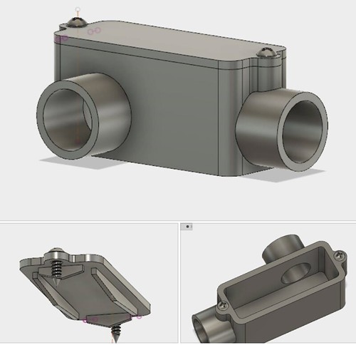
Learning Tinkercad was very easy. Vishal demonstrated the open source online software and we designed our team logos. Even though the program is pretty simple, it makes it very easy to design objects quickly. Our first experience with Fusion 360 was through tutorials before class. Following this series of videos by Lars Christensen, we are able to create a box/housing with a lid. It demonstrated how powerful Fusion 360 really is. We were lucky to have Jeff Smith from Autodesk teach us even more the features available. For my group’s final project, we ended up using Tinkercad rather than Fusion 360 because of its simplicity.

Electronics

Fab Lab:

We spent three consecutive weeks in the Champaign-Urbana Fab Lab. Although I had soldered in the past, it was my first time in several years. It was a great way to practice making circuits and soldering them together. I was also able to code an Arduino for the first time, which sparked my thought process as we brainstormed ideas for our final project. Finally, I also used a laser engraver for the first time. This introduced me to Inkscape, another open source software (have you noticed a theme yet?) that allowed us to take silhouettes and have them etched into the wood and cut through to form edges.

IMG_1468

IMG_1571

IMG_1526

Prototyping:

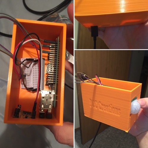
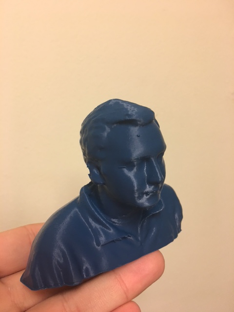
The remainder of the semester focused on prototyping. Although I have been through mock product development phases, this was the first time I have gone from identifying a problem to presenting a final, physical working product. David Kelley says “Design is an iterative process” and I found that to be very true. Our prototype went through many versions starting with a sketch on paper to the final version. Between adjusting our coding on the Raspberry Pi to changing the design of the 3D printed housing to adding and removing functionalities, we spent a lot of time refining the project to best solve the problem of a lack of security on campus while addressing the needs of users. Somewhere in the middle of things we were able to learn about 3D scanning, something we could turn into a business idea as Arielle Rausin has. I was able to scan my head and 3D print it. By the end of the semester, we had been able to design, test, refine, and produce a final security system alternative.


An added bonus of the class was being able to go up to Chicago for a day. We visited Deloitte for a presentation on Deloitte’s tech trends and a consulting workshop. We also visited the Deloitte Greenhouse, a space where clients can come in and run through workshops to problem solve and create connections across many levels of their own companies. It was a really unique space and I’m glad I was able to see it. After Deloitte, we drove over to mHUB, a collaborative space where member companies can work on developing and manufacturing products. This is the epitome of the future of making. Members can work together, building off of each others skill sets, have access to collaborative and shared workspaces, and take advantage of a significant amount of expensive, advanced equipment. It was really cool to see Making on a commercial scale.

IMG_1576

IMG_1581

The end of the semester is bittersweet. While I’m excited for the summer and to be interning again, I am going to miss this class. We formed such a great community together and learned a lot from Vishal, all of our guest speakers, and each other. I’m glad I was able to enjoy this class and challenge myself these past few months.


Idea Coming Toegether

My team and I had a lot of things to get done this past week. We did learn a lot from asking other people what they thought of our design and implementing those thoughts into our design. Although this did put us more towards the beginning of the design development process. Needless to say we had a lot to accomplish.

Our time in class was dedicated to working on our product. My team and I talked about our feedback from others and were able to come to an agreement and create our design on Tinkercad. We came about this by deciding what parts of our product needed to be finalized before we moved onto the next part. Instead of worrying about the material design and testing all at once, we decided one thing at a time. We thought we needed to at least finalize a design.

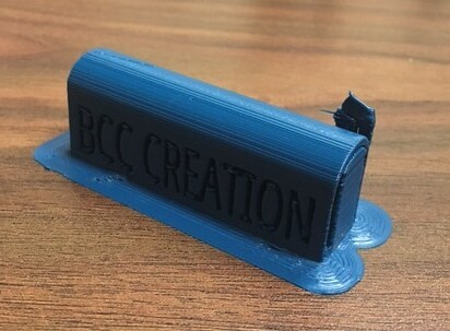
We had gone through a lot of designs. Our final design will be attached to the side of the door and have the ability to slide out to ajar the door and then slide back in and then let the door close. SInce it will be positioned horizontally on the door we do not have to worry about it moving around too much without the user moving it. Also, the moving part will have a handle to make it easy to move the device in and out.

Now that we had finalized we put it on the printer to see if the dementions were correct. In the time our product was printing, we discussed on what materials we think would work best for our product. Our main concern was trying to find a material that would hold up to a door slam. We needed something to absorb the shock a little bit. We thought the base part that is attached to the door could be made out of PLA since it does not come in direct contact with the door. For the sliding part, we think using the material Flex will be the best because we can print it thick and it has some give to it.

We did do trials in class. We wanted to see if the prototype we printed in class would hold up to the door in the MakerLab. Sadly, the door won after a few trials. But we intend to increase the size and density of our product and use the correct materials for the real trials!

Team BCC Creations Designing and Prototyping Reflection

This week we mainly focused on our final project in regards to designing and prototyping. Prior to having group time Vishal had given us resources on the process of prototyping, and reminding us that this would not be the first prototype we would be creating but instead we would keep learning, rebuilding and growing form our prototypes that we create.

My group is Team BCC Creations; we are trying to provide college students with a peace of mind through a cheaper security alternative for their apartments. We have come to a conclusion that many students leave campus during breaks and during those times there are higher chances of trespassing. Thus, we have come up with a “cheap” alarm for a college student, as we don’t have the funds to be purchasing nice alarm systems that some of us may have at our parents’ homes. The alarm can be placed by any door and the alarm will detect whether the door is opened or not. If the door were to open the individual that enters has 5-10 seconds to shut off the alarm before it begins to ring and text the roommates of the apartment. Therefore, unsolicited entry will immediately cause the alarm to ring as well as notify the roommates of the apartment through text messages.

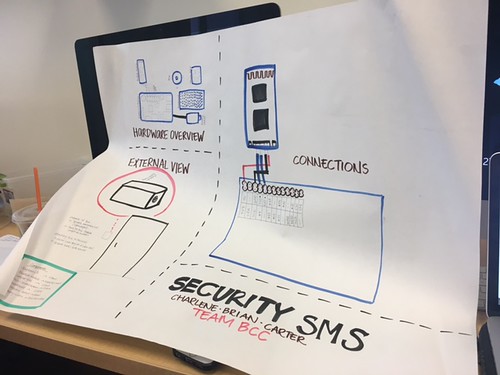
In order to create our alarm we will need a raspberry pi, Twilio, jumper wire, piezo, breadboard, ultrasonic sensor, battery pack, 3D printed housing and Velcro. During our group time we had created a poster that had a diagram of how the components would be connected to each other as well as a sizing guide so we could have a better understanding on how big the housing had to be as well as the alarm system itself. While drawing the diagram we had some concerns on how the parts would fit in but the breadboard gave us more leverage. Because we didn’t have the parts physically in front of us, we still need to approximate some of the components such as the piezo, because we may using a different alternative for the sound system. During class one of our group member had gone to the FabLab to check if they had any Bluetooth modules available for our use, but after speaking with a FabLab assistant we came to an understanding that we could use Twilio as cloud communication platform to send our texts instead of the Bluetooth module which we would need to have Vishal order. The raspberry pi has the capacity to use Wi-Fi and connect with Twilio, so we will still need to test it out but I believe that it could be a very suitable alternative.

After this weeks session we definitely have a better grasp as to how our product will look like, what it will be made of and where to get our components from. I can’t wait to see what we will be able to do in our next class once we have gathered all our components and have them physically laid out in front of us.

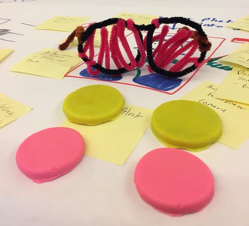
The diagram we had drawn in class.

Our ultrasonic sensor and breadboard.


Soldering & Putting Together The Light Box

Wires are wrapped together and dangle like gruesome tentacles. A foul smoke rises in the air as the iron touches the metal. Silvery blobs form between two pieces of metal. The process of soldering is underway in the laboratory.

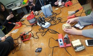
The third and final workshop at the Fab Lab was learning how to solder. I had no prior experience to soldering before, so I was extremely interested. The process of soldering is joining multiple pieces of metals together by melting and adding a filler metal. This results in a permanent connection between electronic components.

Looking back the process was fairly simply. We had to connect all our materials together using a soldering iron. A LED would be connected to a resistor, which would then be connected to a wire. The main concern was using knowing how to safely handle the soldering iron.

The three main safety procedures were to place the soldering iron back into its holder when finished and to never pass the iron to another person, the second was to not breathe in the gas being released when joining metals together, and to wash our hands afterwards since the materials contained lead.

During the workshop, I had difficulty getting the two pieces of metal to stay connected. In addition the metal wires were hard to twist together since they were small. I was one of the last to finish after carefully soldering all the wires together to create an octopus-shaped creature.

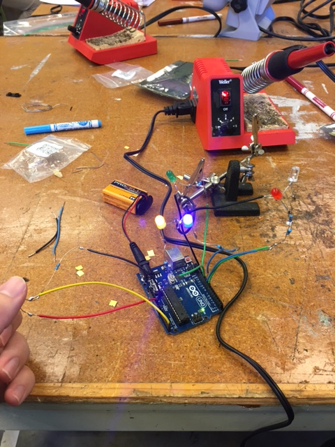
Once the soldering was finished, we tested them on our Arduino boards to see if the LEDs worked properly. Taking my time soldering had paid off as mines did not run into too many issues.

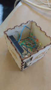
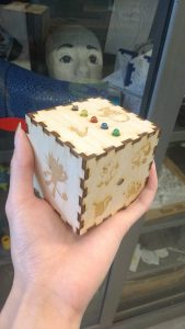
I laid out all of the components for my box on the table and began putting everything together. We had to make sure the wires were not touching one another and that the battery component was sticking out of the backside of the box. A couple drops of hot glue and a few burns later, the Arduino Light Box had been completed!

Instructables provides an easy to follow guide on soldering that can be used to apply these skills for your own project along with other projects that can help you practice your skills. Additional resources include a comic of soldering guidelines by the NASA standard.

Coding, Arduinos, and LEDS, Oh My!

As week 2 of constructing the light up box commenced, we took part in a coding and arduino workshop. Arduinos are electronics made of a combination of hardware and software tools. In our tool kit there was LED lights, an Arduino Uno, jumper wires, a breadboard, and a resistor. The first steps we took were to connect hardware to the Arduino Board.

We had to connect the different components together to create a circuit to allow for the flow of electrons or in other words electricity. I had trouble grasping the concepts at first, but when I started connecting the pieces together, things made more sense. Once we finished connecting the Arduino to the breadboard along with the LEDs, it was time to run some tests on it through software.

We used an Integrated Development Environment (IDE) software to upload a code, or a written text that tells the arduino what to do, onto the LED circuit that we had created. To test whether or not the code was successfully uploaded, we had to check if the LED light was blinking. I found it extremely frustrating trying to edit until the code worked, but once it was successful, I felt extremely satisfied. Afterwards, I had time to practice hacking the code and changing the time and frequency of when the LED would blink.

Overall I found the workshop to be a great first introduction to coding since I had never coded before. While coding is still a daunting skill, I am more motivated to learn it after having played around with it. I believe that coding is an incredible resourceful skill to have going into any industry.

I especially find it inspiration that companies and organizations are reaching out to children to teach and encourage them to code. Girls Who Code is a nonprofit organization dedicated in closing the gender gap in technology; they host after school clubs along with summer immersion programs for girls to learn coding and get exposure to the tech industry. Implementing coding into the fashion industry, Google’s Made with Code initiative allowed for girls to design a black dress with the help of designer Zac Posen and technologist Maddy Maxey.

Designing & Laser Cutting A Box With Inkscape

This past week, we were given a grand tour of the Fab Lab on campus. The Fab Lab is a Maker Space available to students and people within the community. Plentiful of technology are provided at the lab including: work spaces for 3D printing, BioHacking, electronics, sewing to name a few. They offer workshops, summer camps for children, and open hours for you to kick start your projects.

During the next 3 weeks, we will attend different workshops to learn programming, designing, electronics assembly, and more. By the end of the workshops, we will be able to put together an electronic box that can light up depending on certain movements in the environment.

I took part in the designing phase this week, where we used open source software Inkscape to add special features for our box. As a vector graphics editor, Inkscape can also be used for many other purposes, such as sticker designs and creating logos. Using http://boxdesigner.connectionlab.org/, we added parameters as inputs and were given a laser cutting file in .PDF. The file served as a template for our box, which we imported into Inkscape. The shape tool allowed us to add holes and squares to our box template, which would later be used to connect the electronic hardware.

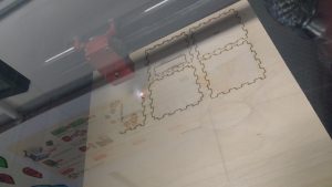
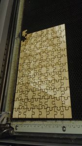
Then, we selected b&w image files online and imported them into the software to rasterize. Once our designs were completed, we sent our files to the laser engraving machine to watch the magic unfold. Our designs from the computer screens were being engraved onto the piece of wood. Another project that was being worked on at another laser machine was an intricate puzzle piece.

Different laser cutters have other properties that allow you to engrave in glass and metal. More complex and intricate designs require more time and high degree precision. In addition, there are machines out there that can cut textiles in a cost efficient way saving resources and time. Small laser cutters & engravers run from a few hundred dollars, while larger machines run in the thousands price range.


I cannot wait to see the final product that will be made with my own two hands. The Fab Lab is a great resource and environment to experiment ideas and learn new skills; I definitely recommend checking it out along with other makerspaces in your area!

Introduction to Intricate Designing

For this week and the upcoming two weeks our class has the privilege of going to the University of Illinois FabLab to learn new tools for our upcoming final project. The first time I had heard about the FabLab was during Jeff Ginger’s presentation during class. I was very intrigued by the different things I could create at the FabLab and was incredibly excited to be able to go and learn from experienced users. When entering the FabLab we were given a tour of the whole facility then split into three groups to begin learning the different tools available. I was assigned to the group led by Holly Brown (Lab Manager and Instructor) and Clinton Gandy (Lab Assistant) to work on creation, design and the process of building boxes through a graphics software called Inkscape.

We had been told that Inkscape would be similar to Adobe Illustrator and I had played around with the application here and there. Throughout class we were given a tutorial box to create, a tutorial of Inkscape and a chance to design our own box that would be laser printed on the wood that was provided by the FabLab. We started by learning the various tools that could be used on Inkscape especially ones that would be useful in designing our boxes, such as grouping and creating holes. Here is a link that gives users an idea of the different features that Inkscape provides: https://inkscape.org/en/about/features/. We then imported the box design onto Inkscape and began adding holes onto one side of the piece that will be used for the lights to shine through in the next two sessions. On another side of the box was a rectangular hole for the battery to come out that would be used for the lights to shine. On the other sides we were able to add our own designs but specifically we were told to use silhouettes of images that could be found through Google. I had chosen silhouettes that I related to personally because I figured it would be more special. Inkscape is a nice introduction graphics software to understand and it was easy to maneuver things around at ease. I really liked how the interface was so simple yet provided an opportunity to draw seamlessly. It was great that imported and exported files could be done through various file formats and overall was comprehensible. I believe that any user is able to use Inkscape to design practically anything. Furthermore, the software allows users to start from the beginning stages to the final stages of a professional design format, which we had created towards the end of class.

After finishing up the box design we had sent them to the laser printer, however, the laser printer took awhile to complete each design and I was not able to watch my design be printed by the end of class. However, when I was watching other student’s designs I was really intrigued with how the lasers had hit the wood to print. The designs were incredibly intricate and we were all amazed with how it was able to print so easily, though it was interesting to see how the laser printer had to be watched carefully at all times in the chance of a fire occurring.

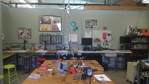
Here is a panoramic of the entrance of the FabLab.

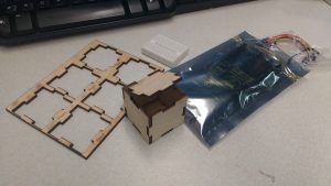
This is the a smaller version of the box we would be creating for practice and putting the box together.

This is the completed tutorial box.

This was an example of what the creation will look like once all the FabLab classes are complete.

Here is the design I had put on one side of the box.

As I stated earlier I was unable to have my design go through the laser printer, but here is how another student, Ian’s design had turned out.

The Ideation Process

In this week’s class our group brainstormed ideas for the semester project. Our main objective during this session was identifying everyday problems that people face. We delved deeper into the process and targeted college students. At the end of the session, our group came up with three How Can We statements:

#1. How can we help young professionals tie a tie more efficiently?

#2. How can we help college students stop losing their items (phones, wallets, and keys)?

#3. How can we help young adults have more optimal audio experience?

Through these statements, we were able to think of products that could address the issues. For example, in addressing statement #2, we came up with a stopper that clips onto the bottom part of a T-shirt and the pant pocket to prevent things from falling out. As a group we decided to spend more time outside class to brainstorm ideas and coming up with more HCW statements. I think the HCW statements are a great starting point for a business idea because they are empathetic to the consumer’s needs and asks a question that can be answered in a variety of ways.

In an article from Science magazine, the authors argue that creativity is more efficient when there is a structure laid out or a framework to follow. The structure is clearly defined and may have constraints imposed. HCW statements fall under this type of creative process, since there is a sentence format to follow. Creating ideas from randomness, while still holding value, is seen as inefficient in problem-solving. I agree with the authors’ statement that creativity is “assessed by  the eyes of the beholder.” I believe both brainstorming creative ideas and coming up with an idea randomly are both effective. However, the ideas will need fine tuning as suggested in this article on evaluating business ideas.

The questions evaluate business ideas by placing them in reality. Are there enough resources? Do they address consumer needs? What are the positives and negatives of this business idea? Once you are able to answer all the questions posed, I believe your ideas will become more concrete and well defined. From this, you can set strategies for moving from the ideation phase to the prototyping phase.

There are several ways to help with the creative process. Forbes suggests individually working out and solving the problems and then meeting with your group to brainstorm. It’s important to note that brainstorming sessions can be ineffective unless certain guidelines are established. Another article from Entrepreneur suggests shying away from the need to be perfect and coming up with as many ideas, even if they’re bad. At the end of the day, I think we should try out whichever creative processes and stick with the one that work better for us.