Smart Light Switch

We designed a smart light switch that allows you to control the light with your cell phone and can be installed hassle-free. Want to know how we came to this idea and realized it? Please keep reading and find our demo in this post!

  • Ideation

In the brainstorming process, we came to a consensus that we all want smart home appliances, such as remote light control, in where we live. However, as renters, we can’t install most of the devices because they require major modifications to the room plus they are expensive. It came to us that although smart home is becoming trendy these days, it is still very costly. Thus, we decided to work on the statement of “How can we make smart home cheaper?”

We further broke down our statement into three design objectives. First, the installation process should be hassle-free. Second, the device can be controlled in distance and no extensive technological knowledge should be required. Third, it should be universally applicable. Bearing those objectives in mind, we decided to make a device to control light. The device can be adhered to the wall on top of the switch and control the switch through mechanical movement. Besides, the device will need to be connected to our smartphones through Bluetooth or Wifi.


  • Market Analysis

Based on our idea, we identified three target customer groups. The first group is short-term home owners, such as college students and young working adults. They won’t own the same room/house for many years, and most likely be unable to make major modifications to the house. Our device will also benefit the large home owners who don’t want to reengineer their house for installation. The third group will be the the elderly and disabled people. The smart light switch can make their lives easier without breaking the budget. Those who are disabled would have the ability to control the light switch without getting up from their seat. In addition to the accessibility, it would also just make it very convenient for pretty much anyone.


  • Initial Design

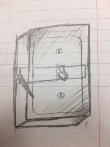
In our initial design, we planned to make a box that could be adhered to the wall with mechanical structures inside to move the switch up and down. We figured out two possible arrangements of the mechanics. The first is to use a combination of rack and pinion (Figure (a)). The rack will have a hole in the middle to fit the switch in. Another design is to have a motor pushes two rods in order to move the switch. The rods are also connected to a lever outside so the switch can still be controlled by the lever. We quickly realized as a team that this would be harder to actually make than we expected.
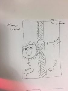
                                    (a)                                            (b)

Figure (a) illustrates the initial rack and pinion design.

Figure (b) is a crude preliminary ideation sketch with a lever on its side.


  • Iterations

We decided to go with the first design initially. The graph below shows the process of 3D printing an enlarged model of rack and pinion.

Animated GIF  - Find & Share on GIPHY

Although the model came out well, when we tried to print the gear in the actual size that we were going to use in our design, we realized that the 3D printer is not able to reach the level of precision we need.

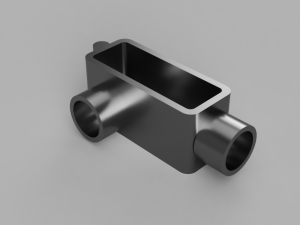
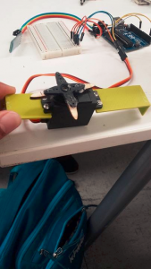
Alternatively, we found out that we could adhere the blade, instead of the pinion, to the motor and pushes the switch directly. The picture below is the motor with the blade. We extended the blade so it adds more contact surface area, making it easier to actually flip the light switch up and down.

  • Final Project Delivery

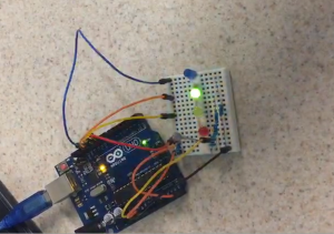
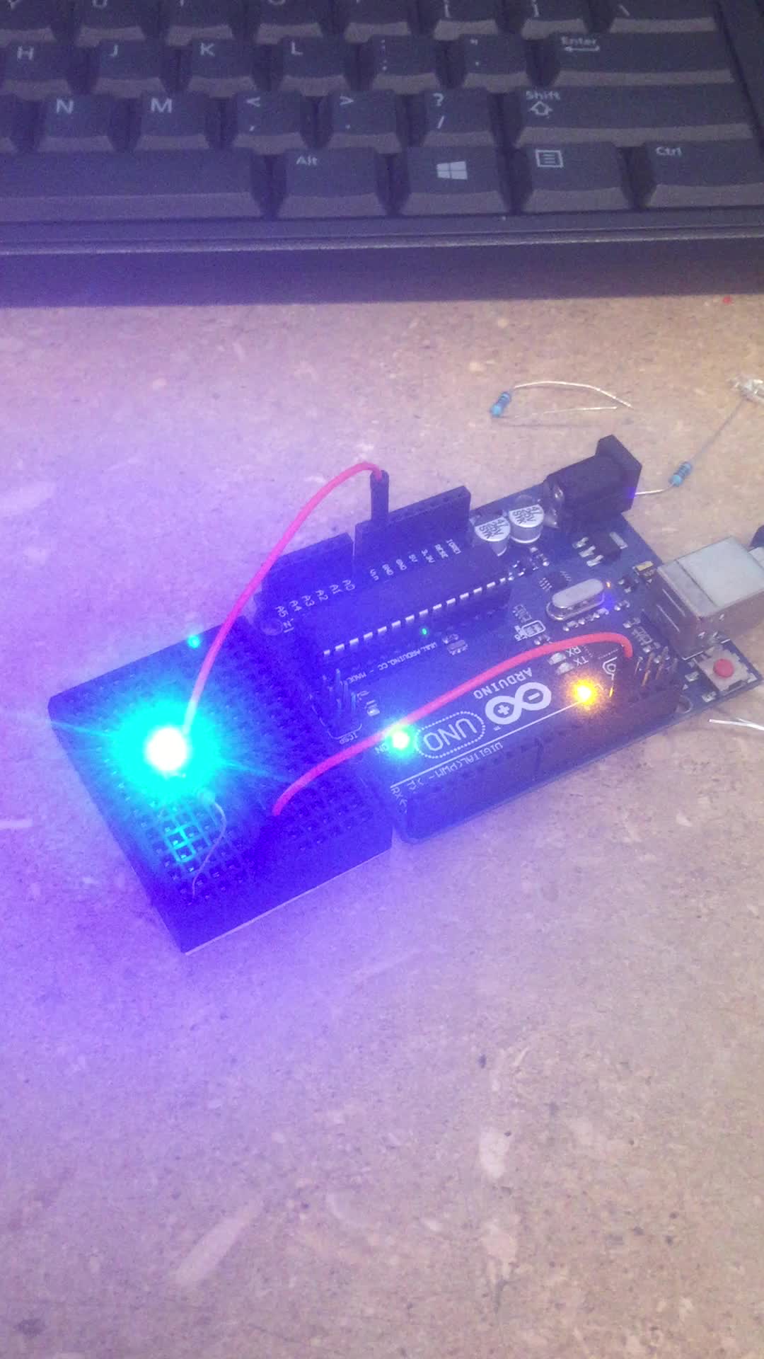
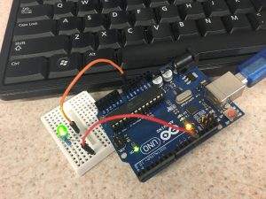
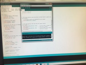
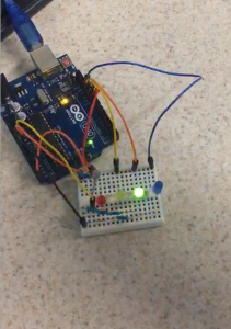
As our final design concept was based on making smart homes cheaper, we had to integrate a system which could control the Motor remotely. By integrating and Arduino Uno and  HC -05 Bluetooth module we programmed the motor to turn to our specifications and also control it remotely.

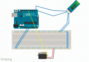
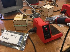
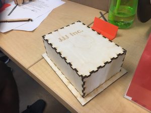
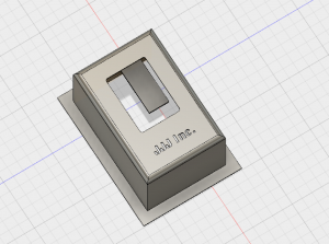
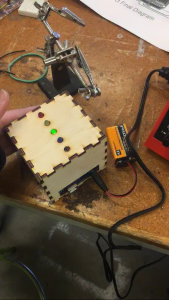
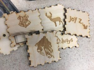
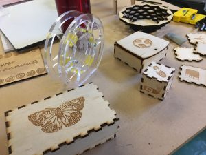
On the picture on the top you can see a Sketch of the Circuit wiring which includes the Motor, the module and the arduino. This sketch was done using Fritzing. The second image is of our final design housing of the light switch. This box was laser cut in the CU Fab lab with our team name embedded in the front! This box was designed in a way so that it mounts directly on top of the light switch and at the same time contains all the wiring inside of it.

In the top most GIF, we successfully were able to wire the Bluetooth module to control the movement of the motor blades!

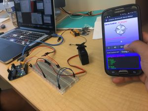
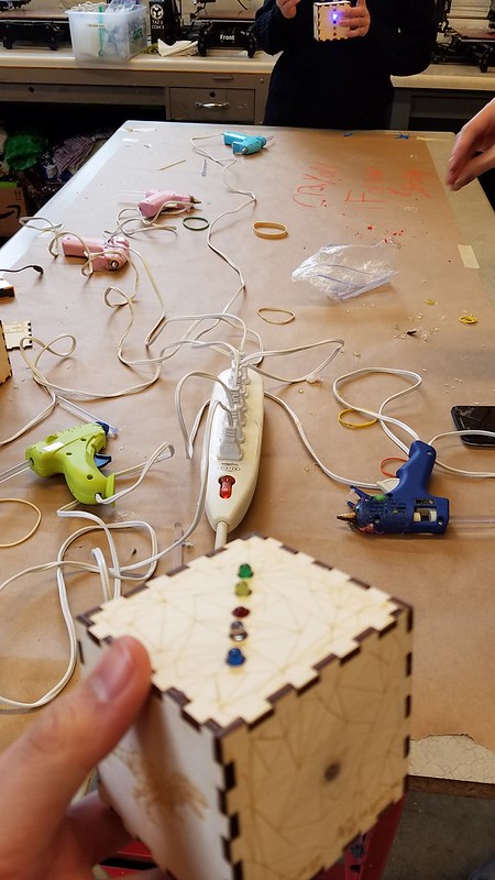
These two GIFs illustrate our prototype at work; switching the light switch on and off with ease.

  • Feedback and Future Work

Some of the feedback we received from friends and some students who used our prototype was geared towards a prototype which could allow the user to not only control the switch remotely but also have an option to manually turn it off and on. Some other suggestions were to make the housing a little bit smaller and easily portable to fit any toggle switch. After thorough research about the types of switches in and around homes, university buildings we found that the toggle (up and down) switch was the most common followed by the rocker as shown in the figures below. Hence, our future work aims towards redesigning the motor blades to increase our usability across all formats. For the research we have done, we have concluded that creating a motor blade to accommodate for the rocker switch would not be incredibly difficult to make, given our current setup.

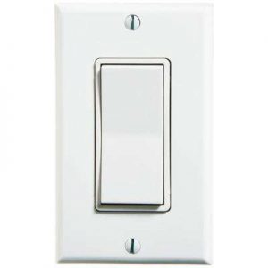
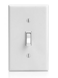
Figure : Rocker switch (left) and the toggle switch (right)

Some of the other future iterations is to use small circuitry by using a custom microprocessor and a watch battery instead of a large 6V battery. This will help us reduce the size of our housing and make our prototype even more user friendly.

Our presentation slides are available here.

Semester Reflection


Expectations

In my freshman year, I took a lesson in material science and explored different 3D printing techniques. I visited the MakerLab at that time but never imagined that I’ll be able to take a lesson in my last semester. After learning that the digital making class will be held in the MakerLab, I’m really excited and applied to take the class to learn more about 3D printing.

Before taking the course, I expect Digital Making will be a interesting class with extensive hands-on experience. Based on the classroom location, I thought this is going to be a class based off 3D designing and printing. I was expecting us learning modeling techniques using softwares and developing business ideas using the 3D modeling and printing.

Experience

As I take on this class, I realized that this class went far beyond my expectation. We not only gained a lot of exposures of 3D printing, but also on other useful skills that can be extremely valuable for entrepreneurship. The skills we learned include but not limited to:

  • Design Thinking
    • We learned design thinking in one of the first few lessons and it benefited me throughout the whole semester. Design thinking is a powerful conceptual tool for designers to figure out what product they are going to make and what are the functionalities mostly wanted by the users. For our term project, we used the design thinking process to determine our project idea and we all believe that it is a crucial part to the success in our project.
  • Designing Software
    • After the ideation process, the designing softwares help the designers to visualize their idea. In the class, we’ve explored several designing softwares, such as TinkerCAD and Fusion 360. TinkerCAD is a web based tool that is easy to learn and operate. Fusion 360 contains more advanced functions and is able to deliver polished rendered graphs. TinkerCAD allows users to build stuff based on the existing building blocks, whereas Fusion 360 allows users to derive 3D models from 2D graphs. Using Fusion 360 is a whole new set of experience to me. In our final project, we used Fusion 360 to build the models (although we didn’t end up using it).
  • 3D Scanning
    • As the inspirational speech from Arielle demonstrated, 3D scanning can help the designers to customize the designs. In the class, we experienced the 3D scanning process with handheld device. We are able to recognize the advantages and things needs attention from the hands-on experience with 3D scanning.
  • Laser Cutter and 3D Printer
    • I learned to use machines such as laser cutter and 3D printer to make prototypes for our design. During the lessons in the FabLab, we learned how does the laser cutter work and its features comparing to other machines.
    • In our final project, we built the housing using a laser cutter because it is fast and convenient. We also tried to use the 3D printer but we didn’t end up using the 3D printed model.
  • Coding and Circuits
    • In the FabLab, we also learned coding with Arduino. We learned how code on the screen can be transferred into the actual LED signal. Besides, we learned how to solder to realize permanent circuit connection. Both of these skills are integrated to our final project.
  • Project Managing
    • We spent a lot of time working on the project and have learned extensive project management skill. Realizing a project idea can be a iterative process that requires us to go back and think over. In addition, teamwork plays an important role in our project experience. It’s important for everyone in the team to utilize their strengths so we could use the time efficiently.
    • Getting feedback is a really beneficial process for our project. From the project audit process, we gained valuable feedback from other teams. From the project tests, we got what our end users think. Both of these processes greatly improved our understanding to the project.

Overall, the Digital Making class brought me great experience picking up new skills, working in the team, and creating incredible things. I learned different ways of thinking and making things. Although I probably won’t be an entrepreneur with my own product produced in the short future, I believe the skills I learned from the class will alter my view as a project manager or product user. What I learned from this class exceeded my expectation and I would recommend this class to anyone who are innovative and enjoy learning!

Project Audit and Assessment

This week, we conducted project audit for two teams. We first audited The MakerLAX’s project, the tie helper. They have several highly finished model. They are going to use a flexible material in the prototype. We believe that they are on the right track to achieve their goal. Another team we audited was the Team Zerott and their robot designed for the MakerLab. They have completed a significant amount of programming using Raspberry Pi. They’ve also designed and created a decent body with wood board to cover the wires and boards. Overall, both teams are under the right track of completing their prototypes.

Our team also made huge progress for our own project —  the Smart Light Switch. Based on our experiments in last week, we decided to use a cross-shaped arm instead of gear. We connected the arm to the motor, and connected the motor to the Arduino board. Then, we connected the bluetooth module to the Arduino board. We found a smartphone application that allows us to control the motor to rotate through bluetooth. This app saved us a lot of hassle.

For the outer box, we’ve created two versions. One is to laser cut one using wood board. We consider this as a “economy” version since it is cheap and time-saving. However, it might need to be larger than needed. Another version we created is the 3D printed box, which is more time consuming but more polished. Both versions allow customization. After testing our motor using the light switch in MakerLab, we found the position to install the motor. Next, we will be mounting the motor to the box. Overall, we are one step from finishing the product.

3D Scanning and Project Updates

In Week 10, we had a class in MakerLab and explored the 3D scanning technology with Arielle Rausin. Afterwards, we moved forward in our team project and tested out the components printed during the session.

3D Scanning Technology

After watching the videos of different types of 3D scanners prior to class, I couldn’t wait to actually see how it works in class. In the class, we were excited to have Arielle again to talk about 3D scanning. Arielle is a previous student from Digital Making class, and she founded a company produce 3D printed racing gloves for wheelchair racers. Back in Week 1, she gave us an overview of how she found the opportunity in 3D technology and built the company. This week, she further explained how she used 3D scanning to build the model she need for 3D printing. She introduced several 3D scanners to us and showed us how to use them. In addition, she demonstrated how to use the software to modify the model generated from the 3D scanner. This function can greatly speed up the process of prototyping based on feedbacks.

Following the demonstration, we took a try in 3D scanning each other in the class. I was surprised by the amount of details it captured and the speed of how it works. The type of scanner we used during the class is very similar to the one in the picture below except ours are desktop version.

Source: https://www.3dsystems.com/shop/sense/techspecs

As showed in the picture, one person will be holding the scanner and person getting scanned will rotate. The person holding the scanner will also be monitoring the progress on the screen and direct the scanned person to move accordingly.

Besides the advantages we found about 3D scanners, we also found the constraints. Because this type of scanner receives the reflected signals to build model, it doesn’t work on the surface with dark colors. One way to solve this problem is to have a person holding a flashlight while scanning. To get the best results of an object, one can paint it in white. In addition, it is easy to have the small item rotates on the plate but it’s hard to have a person rotate as it required. However, what we used is one of the cheapest 3D scanner on the market and more advanced scanners will have less issues.

Project Updates

In the second half of the last class, we continued our experiments for the group project. We printed out an enlarged model of the gear and learned how the gear works. Based on that model and our calculation, we scaled our design. In addition, we tested out the Arduino and motors with the code. We also put the outer case into print. Overall, we got a significant progress and we are on the right track. For the next meeting, we will be connecting the motor with the gear and modifying the outer box based on the size of components.

Project Workshop

Over the past few weeks, we’ve picked up some new skills in the C-U Fab Lab. Now we are going to incorporate those skills into realizing our project idea. Our project requires certain skills and component required from the Fab Lab, thus we went back to the Fab Lab again.

We further determined the details of our project. Our project idea is to create a device that can remotely control the light from smartphones without major renovation of the building. We’ve divided the device into three parts: first is the Bluetooth module, second is the motor driven part that moves the switch up and down, and third is the outer case.

Bluetooth Module

This part’s major function is to communicate with the smartphone. Although we call it the Bluetooth module, we might end up using alternative technologies as well. We initially wants to use a Arduino module with Bluetooth function imbedded, but we are unable to find suitable parts from the Fab Lab. We’ll continue searching for alternatives.

Motor Module

This module consist of a motor and the part moves the switch up and down. We found a motor in the Fab Lab that is able to rotate, and we came up with the idea of the using gear and motor to move a piece of board with a hole in the middle up and down. The switch will come through the hole. We are in the process of designing the gear based on the distance we want it to move. We are planning to print the gear using 3D printers, and cut out the board using the laser cutter.

Outer Case

When we discuss our idea with Prof. Vishal, he recommended us that we can have the case be part of our design as well by allowing customization. This idea inspired us because we know that nobody wants to use our product if looks ugly on the wall. Thus, we started to design the outer case on Fusion 360 and planning to add features to it. Because our design technique on Fusion 360 is limited, I’m looking forward to the next session to elevate my skills.

Next Step

By the end of the class session, we all got our missions clear. We are going to discuss the progress of our respective parts. Next, we are going to test out how each parts works respectively and then start to put parts together. In respect to the design of outer case, we are going to gain additional help from the Fusion 360 expert.

Week 8 Summary: Wrapping Up the Ultra Light Box and More

In week 8, we had our last lesson in the Fab Lab. Same as the past two weeks, we worked on the Ultra Light Box Project in the Fab Lab. The project has three phases: coding, laser-cutting, and soldering. Until this week, everyone has already completed two of the three phases and is ready finalize the Ultra Light Box project. Regarding our term project, we moved one step further and conducted the capability assessment.

Soldering Workshop

Solering table

Animated GIF  - Find & Share on GIPHY

Live action circuit by Ana

A lot of us found soldering skills useful in our term projects. As Ana said, “This soldering workshop really helped me understand the use of soldering. While I was participating in the workshop I thought of how for our final project idea, we will most likely need to solder wires together. ” Soldering is an effective and easy way to connect wires together, and our team is planning to use this technique for our project as well.


Coding Workshop

Picture of Arduino by Taofik

Taofik spent the lesson in the coding workshop using breadboards to build temporary circuits and code on Arduino. Arduino is an open source micro-controller that is easy to code with. Taofik reflected that, “I got to learn more about Arduinos which was a primary reason for taking this class. I will use what I have learned to work on our semester project and will use more tutorials such as Sparkfun’s online website and tutorials and Youtube.”

Laser Engraving Workshop

Laser engraver working (photo by Chase)

Chase designed the print using Inkscape and laser-cut a box. As Chase said, “The whole process, including both the design creations and actual cutting, lasted less than seven minutes, a stark contrast from the relatively lengthy time required for 3D printing.” We learned from this workshop that a faster way of creating a box is using laser engraver.

Wrapping Up

Kenny’s Ultra Light Box

After all three phases were completed, we put the soldered circuits into the box and glued them together. Kenny reflected that “This process got a little frustrating because there were a lot of components that were coming together and a lot of room for error.” I would also agree with him since the room inside the box is tight and it is not so easy to squeeze everything inside without messing up the circuits.

The past three weeks have been a great experience that inspired the class of new perspectives on creating things. As John reflected, “It was really cool to be able to learn so many cool technical skills over the past three weeks, and these skills will prove handy later down the road not only in finishing our semester project, but in future classes and possibly in my job down the road.Learning skills like these can help me turn my ideas into real products that I could sell. With tools like these the possibilities are endless.” This project gave us a lot inspirations on how should we utilize these tools and skills in the future to realize our ideas. Together with the design thinking method we learned earlier in the semester, we are better equipped to start the projects off.

Project Capability Assessment

In prior weeks, we went through the process of brainstorming and narrowed down our selection for our project ideas. After the taking lessons in the Fab Lab for the past three weeks, we developed better perception in the feasibilities of our term project. Thus, we conducted project capability assessments that make sure we have or are able to obtain sufficient capability for our term project. Each team has described their ideas detailedly, evaluated on their project needs, internal capabilities, external capabilities, and source of information.

If, last week, all the projects was still on the conceptual level, all teams have delivered one or more convincing plans this week. In week 7, Team JJJ Inc. illustrated the idea of a simplified smart home device. “Many homes have light switches which operate mechanically by simply moving up and down when subject to an external force. Our product would allow the user to remotely turn the switch up and down using a simple bluetooth device” This week, Team JJJ Inc. described two ways of realizing this idea: one is to use a motor that pulls up and down strings, and another is to using a gear to rotate the switch. Other teams also came up with plans with great details. Based on these plans, they recognized their needs in capabilities.

The internal capabilities are the skills and knowledge that the team possess. Many teams included the skills they learned previously in this class. For instance, Team BCC Creations mentioned that their soldering skills will be needed for their project. Other teams including The MakerLAX

The external capabilities include other sources of help, such as the local labs and other individuals. A lot of teams included the resources that were introduced to us during the class. For instance, Team Zerott included materials provided by Vishal, Fab Lab laser cutter, and the MakerLab 3D printer. Team

Overall, this week we wrapped up our project in the Fab Lab, and we are ready to apply what we learned from the Fab Lab to realize our ideas. Stay tuned for more updates on our projects!


Soldering Circuits

During our third lesson in Fab Lab, I learned soldering skills and finally put together the ultra light box. In the first and second lesson, we engraved a wood board box and designed the circuits in respective lessons. This week, we soldered the circuits and fixed them into the box.

After the first two lessons, I’ve already got myself comfortable working in the Fab Lab. However, I was still nervous when I stood at the soldering station with a soldering gun heating up in front of me.  We first had the parts laid out on the table, and then holding the solder gun near or touching the part. Next, we have the soldering tin near the part, and the soldering tin will melt to the part.

One common mistake for first-timers is that because tin will flow to the higher temperature face, it is important to have the soldering gun touching the part instead of the soldering tin. Otherwise the tin will be left on the soldering gun.

The other concern is the safety issue. When you solder, you need to be very careful with the soldering gun. In addition, you also should try to avoid inhaling the gas. It is crucial to ventilate the room after a period of work. You should also try not to touch anything before washing your hand after doing soldering works. That’s also part of the reason I didn’t have photos with middle processes of my soldering work.

Finally, we have everything ready for the assemble. After testing out the circuits and battery, I started to stuff the box with the circuits. During this process, I had to be gentle in order to avoid breaking any soldered joints. Compared to the other processes, this is the simplest one. After all the work is done, my ultra light box, with my customized prints, will react to the light it sensed and have different patterns of lights.

From the 3-week long learning in the Fab Lab, I gained great hands-on experience of how to make and design things. This is the first time that I build a electric device from the most basic components. To me, it also demystified how things work behind the computer screens a little bit. Most importantly, it helps me to gain necessary skills for building prototypes for our term project. In the future, I’m looking forward to implement the skills I learned into building prototypes.

Coding with Arduino

This is the second lesson that we take in the C-U Community Fab Lab. This week, I picked up the laser engraved wood board and learned coding with Arduino.

In the past, I had very limited exposure to coding. I coded in my freshman year in JavaScript and this semester in SQL, while neither of these experiences were related to electric modules outside of the computer. Therefore, I’m really excited for this opportunity to transform code written on the screen to the Arduino unit that I can see and touch.

We established a basic understanding in coding with Arduino by controlling one LED unit on the board. We first connected the LED with the Arduino board, and then connected it with the computer. One thing needs attention is that each LED has a positive polar and a negative polar, suggested by a longer leg and a shorter leg. In order for it to work, you need to have those legs in the right place.

Then we opened the Arduino coding software and tested it with demonstrative code. Through reading and testing the code, we learned how to control the LED light by using three demand: high voltage, low voltage, and delay. By combining these three demands, we are able to turn the LED on and off, or keep it on and off. After learning how code and Arduino works, we further explored coding by completing a simple task: using the light to convey the Morse code of SOS.

Then we started to test build the circuit for the Light Box, which we will be completing in the next lesson. For the Light Box circuit, we have five LED lights reacting to the distance. Connecting five LED lights and a distance sensing unit to the board is nothing more difficult than connecting one, except for requiring more patience. However, the code became quite hard to understand. I feel lucky that we don’t have to build the entire code from scratch. To understand how does the distance sensing unit works, I opened up the log in software and saw the output from the distance sensing unit. The distance it sensed was transformed to numbers and refreshed (supposedly) in every millisecond.

From this lesson, I gained great experience learning to code and see the output. It’s interesting to see what’s behind the board and how does the distance sensing units work. For our group’s term project, we were thinking about using Arduino when building the prototype. In the next lesson, I’m going to learn soldering the circuit board, and I believe it will be helpful for our term project as well.

Learning in Fab Lab – Laser Engraving

This week, we started our 3-week exploration in CU Community Fab Lab. I’m really impressed with all the cool things going on in this one of the oldest buildings on campus. There are three major parts in the Fab Lab: electronics room, prototyping room, and main lab area. In Fab Lab, we’ve seen exciting projects such as fabric customization, BioHacking and many more that I cannot name. Fab Lab opens to everyone in the Champaign-Urbana community. It’s purpose is not only to create cool stuff, but also to encourage and educate the community with the technology. It offers various programs for youth, professionals, or anyone who are simply interested in creating things.

In this week’s lesson, I experienced the process of designing print for laser-cut boxes. As the photo above, the laser-cut boxes are made from pieces of wood board carved by the laser engraver.

According to Fab Lab’s website, the laser engravers are their most popular type of tool. From my own experience, I can totally see why it’s so popular. Compared to 3D printing, laser engraving is a reversed way of creating new things. Instead of stacking materials together to build an item, laser engravers takes away unneeded material and cut out connecting structures. Therefore, if you want to build a box, using laser engravers will be much faster. In addition, laser engravers can create extremely delicate patterns, which is hard to achieve using 3D printers. Last but not least, the skills needed for creating print or customization is easy for beginners to pick up. Laser engravers read PDF files, so instead of building a 3D model and using softwares to slice it to 2D prints, users can design prints for laser engravers using any vectogram editing softwares. The software we used during the workshop is InkScape, an open-source software that is free and powerful. It is easier to handle compared with TinkerCad and Fusion 360.

The process of creating the print for a box is simple as we learned in the workshop. After having the picture of the box you want to design in your mind, you can go to any websites that offer free customized box print (for instance this websiste). Then you can put your design on any faces of the box. The machines recognize certain colors, so it’s important to make sure the color settings are correct in your print. After saving your print as PDF, you can direct the engraver to the file to get started. One thing noticeable is that unlike using a 3D printer, you need to watch the engraver while it works in case of it (or the wood) catch on fire.

During the session, I’ve put together my design. In the next session, I’ll have my design printed out and assembled. Besides designing the box, I also tried to assemble a box printed out by Fab Lab.

Looking forward, I think the laser engraver can be a powerful tool for both designing prototypes (and making customized gift boxes). If a designer has a clear idea of what his or her design should be laid out on a flat face, it is easier to use laser engraver to build their prototypes than using 3D printer. In the future, I look forward to using laser engraver to realize my project ideas.

Initial Project Scoping

In this lesson, we implemented the first stage of the “design thinking” process that we learned in previous sessions for our term project. Each team in the class was asked to come up with three “How can we” statements. The point of this procedure is to identify problems that could possibly be solved with our skills. It doesn’t have to affect a huge population, while it must address some problem that bothers people in real life.

In the given 30 minutes during the class, we identified three problems came from our lives as college students:

How can we save water when cleaning dishes?

First problem we identified is that too much water was wasted when we wash dishes by hands. A considerable amount of water was not utilized effectively when we rinse the dishes. As we all agreed, our concern in this issue is to save resource and energy instead of water bill.

When we moved forward to think about possible solutions, we were inspired by a product design on kickstarter.com, which pulverizes water stream. Our team thinks we could build on that idea and design a product that works with different types of home-use or commercial faucets. We will be continue working on brainstorming solutions in the following meetings.

How can we make smart home more affordable and hassle-free?

When we were discussing what else problem we have in our life, we came to a consensus that it is really annoying when we realized the light was still on after we jumped to our beds at nights. All of us really want to control the light remotely from our phones. However, as renters, we can’t install the device in the wall. Therefore, it came to us that although smart home is becoming trendy these days, it is still inapplicable to a lot of people, such as renters and people lack of technical capabilities. In addition, the prices of smart home are high for non-tech fans. For instance, Phillips Hue Starter Pack costs $200 without handling fees (more information). How can we make smart home accessible to more people?

One possible solution we came up at the first stage is to have a device that can be adhered to the wall on top of the switch and control the switch through mechanical movement. The device can be connected to the phone through bluetooth or wifi. This approach allows hassle-free installation and is zero knowledge required. We will probably dive deeper into this idea in the later process.

How can we prevent heat from leaking through window while allowing us to open window during winter time?

In winter, a lot of us may have sealed their window trying to prevent heat to come out. However, it might not work effectively due to uneven faces. Meanwhile, it also prevents us from opening the window when weather became nice temporarily (like last week). Therefore, we think it’s a problem that might have a better solution. We will continue brainstorming the solutions in future sessions.

Next Step

As I mentioned above, we will continue our “design thinking” process in the future. We will brainstorm solutions for each “How can we” statement and choose one for term project based on the our skill sets and what we learned in the reading “10 Ways To Evaluate A New Business Idea”.