3D Scanning and Project Progression

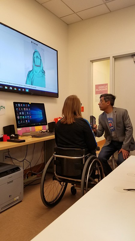
This week we returned to the MakerLab after a three-part tutorial series at the Champaign-Urbana Fab Lab. Before continuing work on our final semester projects, Arielle stopped by again and instructed us on how to effectively utilize a 3D scanner. This technology, she explained, helped her tremendously with making changes to the wheelchair glove that she has been making. Essentially, 3D scanners utilize lasers to scan every part of an object, which is then overlayed together by scanning software to create a 3D model. One software that was spotlighted during the workshop was yet another Autodesk product called Meshmixer, a relatively easy-to-use scanning software that allows the user to edit the scanned model before exporting the file to be 3D printed or added to other parts. Common types of editing include smoothing out certain areas of the model, extruding sides, or cropping unnecessary parts of the scan.

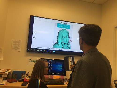
Arielle explaining one of the intricacies of Meshmixer as it pertains to her product:

After her presentation, we were allowed to try our own hand at 3D scanning using a mobile scanner. While Arielle made the process look painless, we quickly encountered a variety of challenges when attempting to scan our objects (our own heads). Firstly, the scanner struggled to pick up certain complex features of the face, such as specific details of the eyes and ears. Next, the scanner required very strong lighting, as the lasers it employed required light to bounce off the object, similar to a camera. This led to another hurdle; any users wearing dark clothing, such as a black jacket or shirt, struggled to obtain an accurate scan below their neckline. As with many obstacles faced throughout the course, over time and with much practice we were able to overcome these complications. Once scanned, we first cropped unnecessary features from the scan and solidified aspects of the object that were not properly scanned. From there, we imported the solidified 3D model busts into Cura to finalize before being printed.

An example of Peter’s bust after being exported into Cura:

For reference, here’s a simple and quick tutorial on Autodesk’s Meshmixer:

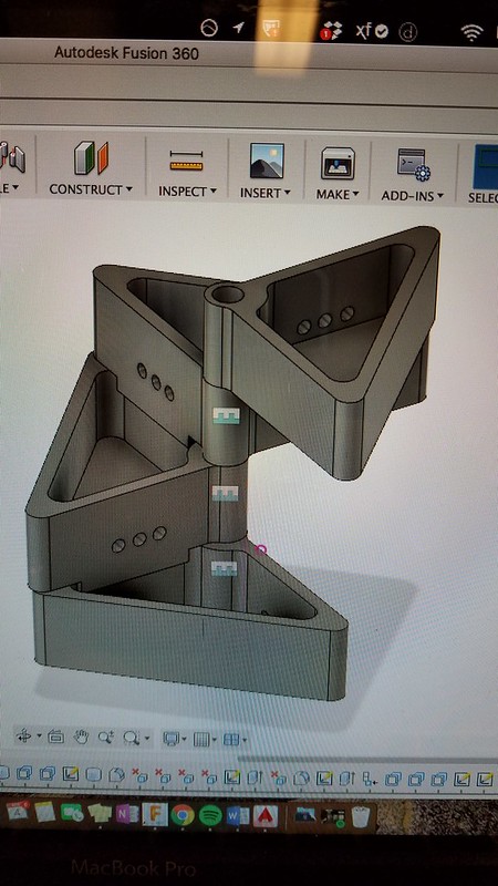
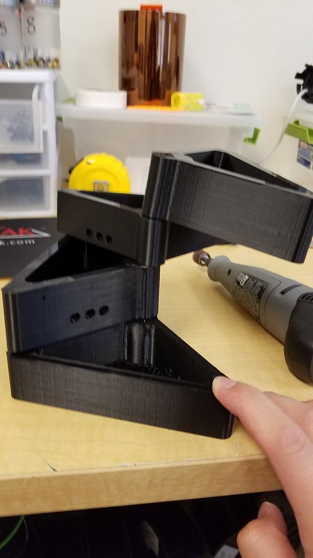
After taking a shot at 3D scanning, we returned to focus on our group projects. Our group, Team MakerLax, was able to create the initial model of our product using both Autodesk’s Fusion 360 and TinkerCAD. This first prototype certainly leaves much to be desired as there are a variety of adjustments to be made, however I am glad we were able to design a preliminary model. This way, we understand the direction that we are headed in and can add or subtract features accordingly. I look forward to adding a few more features to the product this upcoming week.

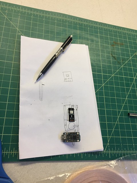
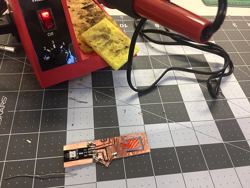
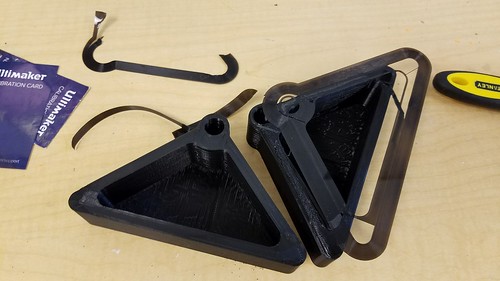
The initial prototype of our “Tie Helper”:

3D Scanning & Second Prototype

The topic for last week lecture was 3D scanning. We had Arielle Rausin, the founder of Ingenium Manufacturing, to give us a detailed demonstration of two different types of 3D scanning technologies. The first type of 3D scanning required the object to be placed on a round platform. As the platform rotated, the camera on the side would measure the dimension of the object on the platform. Due to the time limitation, Arielle shortened the time for the camera to gather enough data. Thus, unfortunately, we did not get a normal 3D image by utilizing this technology. The second technology was much more flexible comparing to the first one. We held a scanner in front of the person/ object we wanted to scan. Meanwhile, the computer would use the data transferred from the scanner to create instantaneous 3D image. Because we could see the temporary 3D image, we could focus more on the part that computer could not generate image properly.

IMG_4080


IMG_4081


The final deliverable for our group is a dehydration detection wrap and we would design the wrap by ourselves, so there was no need for us to use the 3D scanning technology in our project. Last time, we made a cardboard prototype and this time we would make a wrap that could actually detect the humidity of the skin.

IMG_4129


IMG_4131

It was time to go back Fab Lab and work with Brandon, our technical consultant who worked in Fab Lab. This time, we started to draw the circuit on paper to visualize our idea first. Then, we discussed the possible solutions minimize the circuit based on the blueprint we drew. After we finalized the blueprint, we used the copper coil as the motherboard. Then, we carved out the coil by following the circuit map we draw. Once the motherboard was ready, we placed the controller, mini-Arduino, on it and solder the controller to the board. I had to mention that it was extremely hard and time-consuming to solder the controller and copper coil together. Luckily, we made it in the end. In the following week, we would install the sensor and code the program for the controller. Hopefully, we could have a functional prototype by the end of this upcoming week!

IMG_4133

A reiterative process of trial and error

The progression of our ideas came to fruition this week as we heavily began idealizing and seeing how all of the parts of our design come together. The first half of this week’s class was allotted to learning 3D scanning from Ariel utilizing a handheld model. We then proceeded to scan our heads as well however, we learned that the scanner does not like dark surfaces and so we had to scan black hair with a phone light.

20170403_144847

The next half of class we were heavily involved in redefining our project’s components with an initial rough print. This taught us that we need to prototype fast and quickly due to the nature of how 3D printing is not perfect and it is a reiterative process in order to perfect a design. We continuously developed our design and got an idea of how to make these modules separate in the case if we want to add more or less at any given time. The Fusion 360 model below shows how we visualized our final product.

IMG1740895582

However, once we started printing, the holes did not line up correctly and sometimes the printer was having trouble with misalignment or if the filament ran out mid print as that happened to our initial prints.

20170405_150355

Then after another run through the printer we were able to narrow down the problems, address it and throw in another print. This one proved to be a much more successful model but it still did not stand up on its own which was cause for concern for us since we need it to be able to not only support its own weight but it needs to support, clay rocks, plants and moving water.

20170405_154052

Upon doing further research we found a great resource named “The Aquaponics Source” and it helped narrow down what type of plants, planting media as well as the conditions that are needed to keep our plants happy and healthy.

The next stages that I determined to be instrumental for the project is constructing the actual tank from 1/4″ acrylic sheets from the FabLab but they only had 1 clear one left and that was not enough since they were only 12″ x 24″ and so they are in the process of ordering more and it will come in about 10 days, which will hopefully give us time to cure and test our product. But I was able to use that one sheet and start dimensioning and designing the tank.

20170405_171649

20170405_173155

Our next step is to wait for all of the components we ordered to get here on time, which is the fish pump, tubing, finish printing the modules, as well as waiting for the acrylic to arrive and slowly put it together.