Category Archives: Uncategorized

Week 11 In Review

Week 11 brought our class a full period of time to work on our group projects. Each group worked diligently on their projects for two hours before coming together and updating the class on the progress made. Each project seems to be coming along nicely for all of our groups, with a wide-ranging spectrum of objectives. Because we had no guest speaker or other new learnings this week, the week’s summary will focus on each group project’s prototype development.

Steering Wheel Attachment

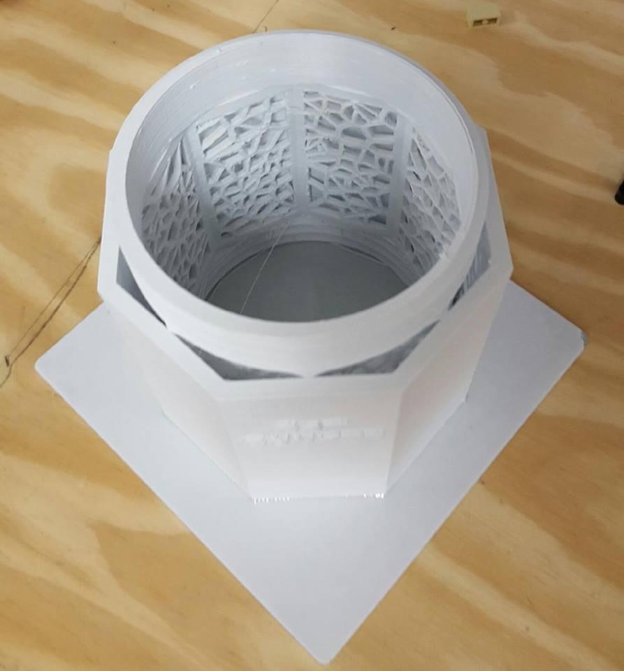
The steering wheel attachment team (my group) began printing the key components of the base clamp for the device designed to ease the steering of physically impaired drivers. The group printed two major components successfully and added attachments to be finished printing after the class ended. Once all parts are printed successfully, the group plans to assemble the pieces and create the first version of the steering wheel attachments. Then, they’ll make modifications as necessary.

People Counter

The people counter team made excellent progress towards a working prototype this week when they successfully uploaded code to an Arduino. The group was able to get lights to blink at the push of a button, one step closer to achieving a light upon the passing by of a sensor. The group is now focusing on tackling that challenge in addition to the storing of values so that entrants may be tracked over time by store owners.

Hydroponic Vertical Garden

The first of our two vertical garden teams worked with MeshMixer to design printable housing parts to hold the indoor plants. The group successfully printed a drip nozzle and bottle cage and is looking forward to completing their prototyping pieces next week. This team realized it should shift their prototype to house four plants instead of eight upon learning how long their prints would take.

Customizable Earphone Grips

Team synergy recently made a pivot in their project direction when they learned that their solar-powered hot plate would not create enough energy to keep a beverage warm. Pivoting is a part of the design process, and this group made an excellent decision in abandoning its old idea once they knew it would not be sustainable.  The team has decided now to create customizable earphone grips that clip onto any pair of headphones and secure onto the ears of the user.

Coffee Pour Over Assistant

The coffee pour team is creating a system to easily pour coffee without human assistance. This week they decided to divide their system into two halves, top and bottom. They printed slides that the coffee can flow through as a placeholder until they can find a material that can better withstand hot water.

Vertical Garden

The second vertical garden team is building a garden to grow small plants and printed a base that will catch water. There are multiple pots in this garden with columns to hold up each pot and a box for Arduino sensors. They completed some of the wirings for their box as well as the printed base for the entire product during the week and are moving forward in their prototyping phase nicely.

Weekly Reading

Our weekly reading ties in quite closely with our work in class. The article discusses the many steps of prototyping: Finding test subjects, preparing the test, the test environment, testing, and updating the prototype.

As a class, we are in the ‘preparing the test’ phase during which we are printing the necessary materials and determining the testing subjects needed in order to successfully begin the test. Last week, each group finalized a project testing plan outlining who their subjects are, and how they would administer the test. In highlighting the ‘preparing the test’ phase, Marty Cagan writes about making assumptions and asking the right questions. These two ideas go hand-in-hand because asking the right questions allows project testers to eliminate their biased assumptions. These assumptions can become the demise of a project, which may not be solving the right problem in the first place.

Cagan also suggests asking initial testers what they might be willing to pay for a product if upgraded beyond the initial prototype. This allows creators to get a gauge of the value of what their product. Later on, the article stresses the importance of updating the prototype once feedback is obtained. Everything we have learned up to this point indicates that the best method to successful prototyping is to do so quickly, without worrying about perfecting the design. The faster we can prototype, the faster we can obtain feedback, and the faster we can improve upon our designs.


Week 12 – Prototyping and Planning

This week, I was stuck at home during class time due to a stomach bug. Despite this setback, I am much happier with the current position my team is in given the challenges we have faced. Our original idea of a solar-powered drink warmer was not feasible because the power generated from the solar panel would not be adequate. If we wanted to have adequate power, we would need to wire the circuit with a nine-volt battery. However, adding a battery to the project reduced the novelty of the project. Upon consulting with the experts at the UIUC FabLab, we decided to bring our project into a different direction. My groupmate Ria, from Team Synergy, had a great idea to solve a common problem. Currently, the Apple Air Pods rest on the lower inner ear and are connected via Bluetooth to the iPhone. However, when consumers try to use the Apple Air Pods while working out, running, or any other strenuous activity, the Air Pods are prone to falling out of the ear. To prevent this, our project aims to stabilize the Air Pods by printing an attachment to keep the Air Pods in the ears.

PICTURE

The design will feature an attachment clip to the base of the Air Pod. This will wrap around the Air Pod and secure the stabilizing mechanism. The stabilizing mechanism is a 3D printed tube that wraps around the outside of the ear. Although we were not having great success with 3D scanning someone’s head and isolating the ears, we were able to come up with a makeshift solution. We would like to make three different sizes of Air Pod holders, small, medium, and large. This will allow us to quickly make the Air Pod holders from a set of premade molds, rather than scanning someone’s head every time we want to print the holders. We visited the UIUC FabLab to talk to Clinton about our idea and he gave us a lot of great feedback. Clinton showed us how to make a spline, an arc made of multiple non-colinear points. Once we made a spline, we used the sweep feature to give depth to our arc. When the stabilizing mechanism design was finished, we attached it to our attachment clip to finish the design. We did not get a chance to print out our prototype, so we will be visiting the MakerLab on Monday to print out a beginning prototype. More to come from Team Synergy!

Initial Prototyping

This week in class we were able to make a lot of progress on all of our projects. Although only 2 of us were there out of our group, we made an initial design for our coffee pour over assistant. We decided to separate the product into two parts. The bottom part, which consists of the four legs that support the object and it is also where you place the filter and coffee grinds. It was difficult to decide how tall to make it because coffee cups are all different sizes. Ultimately, we decided to make this portion of the product customizable so when we make the design open to everyone, the person printing it can decide how tall they want to make the legs. The picture shows the beginning of the 3D print for the bottom half of the assistant.

We were also able to cut out the part for the coffee filter pretty easily. We simply cut a filter into the top part of the bottom half. Next, we began work on the top half of the coffee pour over assistant. This is where the user will pour the water and it will slowly drip over the coffee grinds. We decided to have two slides that the water will drip through. The top one has several larger holes placed around the circle to slow down the water a little bit. The next slide will consist of much smaller holes which will control the water flow much more. The picture shows the beginning of the 3D print for the larger holes that the water will flow through. Because this is a prototype we printed it with the material in the MakerLab. When we create our final product we will use a different material that can withstand hot water over several uses.

I was doing some research to find out which materials people use in the 3D printing world to use with hot water. I found a website with a discussion on the topic. I think I will also go to the FabLab and talk with the gurus there to see what they think would be the best material to use.

In the upcoming weeks my group plans to test our product with users and see what we need to change with the original design. We will also gather material to use for the top half of the design that can withstand the hot water and not potentially leak toxins into the water. More to come in the upcoming weeks!

Prototyping After a Pivot

After some deliberation, my group (Team Synergy) has decided to pursue a different project idea. We realized that our original design for a solar-powered hot plate would not be able to generate a sufficient amount of energy to keep a beverage warm, so we decided to switch gears and try to make customizable earphone grips instead.

We’ve begun the prototyping process in efforts to catch up with the rest of the class, and are playing around with multiple ideas as of now. While we don’t have photos to share as yet, we’re trying to create something that will clip onto any pair of earphones and then wrap around the user’s ear to hold it in place. We were hoping to get the exact measurements of each users’ ear so that the grip has a customized fit. The original idea was to use 3D scans of each ear to come up with the right size grip to print, however, we realized that the scans have to be re-scaled anyway so there was no point in adding an additional step. We are now thinking of coming up with a base design and then tweaking it according to measurements we take by hand for each user.

Despite the fact that we’re behind schedule, I am trying to remind myself that our prototype does not need to be perfect when we test it for the first time. As the “Prototype Testing” article from SVPG advises, I think we’re going to have to rely on a highly iterative process of getting feedback and implementing changes before quickly retesting the product. It’s also very important for us to keep the test subjects in “use mode” as opposed to “critique mode” as the article suggests. We want to identify what will help make the product serve an actual use case, and then reposition it accordingly.

I’m looking forward to the next few days of prototyping and testing—we will certainly have more updates to share by next week!

Building & Testing (Week 12)

Hello, everyone!

This week, my group focused on building our working prototype and uploading our code to the Arduino board. We spent past weeks learning what the laser sensors were, how the Arduino worked, and really getting an idea of how the more complicated pieces in our people counter operate. However, when we started to put the first working model together, we found that we had missed learning about some of the little things! Is there a positive and negative end to the LEDs? Can we connect resistors to each other? Can we put the resistors directly on the Arduino or do we need to put them on the perf-board? Does it matter?!

We learned that it’s important not to overlook these little things, but we were able to figure them out as we went. We did not have a 470 ohm resistor (called for in our guide), so we connected 2 resitors of lessor values to get to that 470 ohms. Here is the website we used to learn how to determine how much resistance one resistor has. If you didn’t know, ohm resistors use colored bands to show the user what resistance they carry. You read the bands left to right – each color has a number attached to it. Below is a chart you can look at o determine what resistance your resistor might have.

Since our 7-digit display had not yet arrived,  we made our first working prototype with individual LEDs. A 7-digit display is just many LEDs put together in a particular oder. Organization of the lights aside, connecting a few LEDs to our perf board allowed us to get a similar effect.

We were able to upload our code to the Arduino and connect all the wires we needed to. We did not have a battery on hand, but we used the Arduino connector in conjunction with a 5V cell phone converter and plugged the counter into the wall socket. Regular sockets run at about 120V, so it was important to have the converter in order to not overload our creation.

We were able to hook up the counter to power and run the program – we made a few of the LEDs blink! We are currently using the push button, not the laser sensors, so every time I pushed the button, we’d have a light blink. It was gratifying to see all our wire connecting and learnings pay off.

Another thing my group discussed was memory. An Arduino can hold the memory of the program its running, but needs extra memory to hold anything else. If we want our counter to hold historical data, we have to add a chip or another board to our Arduino. This will require us to solder some wires, so we will look more into this next week. I found this forum online discussing Arduino memory that has been helpful to me. It might also be helpful to groups also using Arduinos.

Tangible Prototyping

Assigned Reading

This week’s assigned reading was all about the process behind prototype testing. I really learned a lot from this resource that I did not know before about the development/testing stages of a product build. One that that stuck out to me is three important use cases I need to be looking out for when I observe participants: “the user got through the task with no problem at all and no help; the user struggled and moaned a bit but he eventually got through it; he got so frustrated he gave up.”

Each of these categories provide valuable insight into understanding how a given test subject interacts with the product we created. In our case, with our steering wheel assist tool, we will be closely monitoring our test subjects in a closed environment (parking lot) to observe the way they install and use the tool. It was helpful to understand more insights behind testing.

Class Reflection

In class this week, we finally  started printing actual prototypes of our steering assist tool – it was awesome to actually hold our idea in our hands. We have 5 pieces of the total project we need to print out:
1. Bushing (printed)
2. Screw (printed)
3. Handle Attachment 1 (printed, in the lab)
4. Bracket (printed, in the lab)
5. Handle Attachment 2 (need to print)
We are excited with our progress so far. Here is what the screw looks like. We were surprised by just how strong this screw actually was. After printing this prototype, we realized we will likely need to extend the length of this screw a little longer to accommodate our handle attachments.
Furthermore, we were able to print the bushing that will serve to tighten the bracket that attaches to the steering wheel. The interesting thing about the bushing is the way that it bends when it is compressed, rather than staying rigid. This will allow the screw to secure into place without cracking under the pressure.
When we come back into the lab, we plan on assembling all the parts we have on hand. We will likely need to make slight modifications to the steering wheel attachments, and start prototype testing as soon as we are able to! We are looking forward to seeing how our steering assist tool will actually function in a testing environment. Can’t wait to get back into the lab this week to continue prototyping.

3D Printing: Making Music More Accessible (Once A Semester Activity)

Throughout my semester in the Digital Making Seminar, I have been thinking about 3D printing and music. I am a musician myself, as are my parents and many others in my extended family. I was fortunate enough to attend a school and come from a family where instruments were provided to me from the very beginning. As I progressed both in age and ability, the quality of my instruments did as well. I am a percussionist, so not only did my instrument need upgrading as my skills grew (like any musician), but all of my instruments needed upgrading. My school had most of the percussion instruments called “toys” and other small instruments I could practice on, but I owned my own marimba, drum set, and concert drums. For any instrumentalist (and a percussionist in particular), the cost of upgrading instruments (or even buying them in the first place) is staggering.

I’d seen plastic trombones and trumpets at music conventions before – I knew that brass wasn’t the only material that could be used to make those instruments. I’d seen cheaper, plastic tambourines, flutes, and other instruments before, so I knew it could be done. But this class got me thinking – could they be 3D printed? And furthermore, could this be a way to introduce entry-level instruments to beginning musicians from underserved schools?

My mom used to do instrument contracting with Quilan & Fabish, a music company that sells and rents out instruments primarily to schools in the Midwest. To rent the lowest grade, entry-level trombone, the cost is nearly $40 per month. If a student is in school for 7 months, that’s $280. If they practice over the summer, that’s $480. Many underserved schools don’t have the budget to buy instruments outright and rent them to students cost-free as my middle and high schools did. These underserved schools often have to fight for the budget for a music program, so you can imagine how absurd a teacher requesting 12 trombones plus any other instruments for the students might be. Additionally, many of the parents of these children in underserved schools do not have the money to rent or purchase the instruments. My mom recounts visiting several underfunded schools in the Chicago Public School system with Quinlan & Fabish and watching parents take their children home empty-handed from the instrument try-out session because they could not afford the instrument.

There have been plenty of studies pointing to the benefits of music and the arts in childhood development (you can download and read some of those studies here, here and here). The National Association of Music Merchants has reported that music programs in schools keep students engaged in the classroom, improve early cognitive development as well as math and reading skills, and develop critical thinking skills. These findings all point to an obvious course of action – making sure public schools offer music programs – but the stark reality is that music is often one of the first things to be cut, from both the parent’s budget and the school’s. According to Children’s Music Workshop, 1.3 million elementary schools do not have access to music classes or band/choir programs. That is why I’d like to take the rest of this activity to explore how 3D printing may be able to bridge this gap and provide children with the affordable instruments they deserve.

***

Currently, 3D printing and the music industry are intertwined, but not in the way that would bridge the previously mentioned music education gap. Artists and musicians are collaborating to produce instruments or shells for instruments with interesting designs and patterns. Below, you can see the 3D printed body of an electric guitar and the 3D printed shells of a drum set. The last picture is of the shell of an electric keyboard. In this case, 3D printing has only been used to enhance the beauty of the instrument – making it novel and futuristic, but unfortunately, not bringing down its cost. As you can tell form these exhibits, 3D printing can be found in the world of music, but not quite in the capacity I had originally hoped.


Guitar (Picture from Created Digital Music)

 Drum Set (Picture from 3D Printing News)

Piano (Picture from 3D Printing News)

***

I did find some 3D printed instruments that were more targeted towards function rather than form – this is the research an idea like mine would need in order to begin developing more realistic instruments (rather than the whimsical ones we see above). Here is a Thingaverse file for a 3D printed ukulele. A video of the creator playing the final product can be found here. However, the ukulele and many of the other instrument files available on Thingiverse are more eclectic than they are useful. A school band program does not have ukuleles or ocarinas. These programs need violins, flutes, brass, and other traditional instruments that can be found in band and orchestral music.

Outside of Thingiverse, I stumbled across a very special company: Hola. Using Autodesk’s Fusion 360 software, Hola has created a full-sized, completely playable violin. The company has demoed the instrument at conventions and online. Hola has also made the file open-source. The company calls this violin the Holavin. And, with correct strings and tuning, the Holavin sounds really good! Here is a video of Kaitlyn Hova, the founder of the company/Hovalin, playing her 3D printed instrument. And here is a video of an 11-year old who printed and now plays his own Hovalin.

Hovalin Picture

On Quilan & Fanish’s website, a beginner violin can be rented for $69 per month. For An entire school year and summer, that is $828. The Hovalin can be printed for around $70. The printer it can be made on is about $600. The printer and materials combined are less than a year or renting (towards the purchase of) a beginner violin. And once the printer is purchased, many violins can be printed. This is so exciting, because the Hovalin is the first real example of an expensive, traditional instrument being produced at an extremely low-cost with only a small reduction in quality. Keep in mind that usually, no beginner instrument for children will be high quality. The purpose of the instrument is to teach fingering, notes, rhythm, and technique. If a child continues to play and improve, higher quality instruments will follow. But the Hovalin will do just fine for a school of students who don’t have anything at the movement.

***

There is not much research or many open-source files of working, 3D printed instruments out there, but the Hovalin proves it can be done. If this momentum in the music/3D printing world continues, there is hope that one day, all children will have the opportunity to pick up an instrument.

Initial prototypes and Designing

Bust

Last week, I was not able to create my 3D Printed bust but I was able to do so this week! A classmate took a scan of myself that I uploaded onto Meshmixer. The original scan had some creaks and empty spaces but Meshmixer did a great job editing the scan. I was able to close the STL file by simply selecting a function called Make Solid and Close Cracks. Afterwards, I exported the file and opened it in Cura. The file was to small to be seen so I then selected all and scaled the item up (10000). After making some other edits in Cura, I then began the 3d printing process. In total, by bust took 45 minutes to print and I am thrilled with the results!

FaceBack
Project: Hydroponic Vertical Garden

This weeks class was mainly devoted on creating the initial prototypes of our final project. My part in the project is to create a voronoi patterned bottle holder to fit a 2 liter as well as drip nozzles.  I spent most of the weekend researching this history of voronoi diagrams and the results of my findings can be found in my last blog.

https://publish.illinois.edu/digitalmaking2018/2018/04/09/once-a-semester-project-voronoi-pattern/ 

I went to the FabLab in hopes of finding someone skilled in Meshmixer to help me with parts I found difficult, but the students there were more familiar with other softwares. Thus, I went to Youtube and found great tutorials! After familiarizing myself with Meshmixer, I really enjoyed working with the software and created a wonderful bottle cage that I initially felt apprehensive about.

Bottle Cage

I was able to print the drip nozzle and the bottle cage. The drip nozzle was printed in less than an hour. Whereas, the bottle cage holder took nearly 20 hours to print! Initially, our team 3Dream wanted to have 8 plants but after taking into consideration how long it takes to print one bottle cage holder, we will now print 4 of them and 4 drip nozzles.

Thank you for taking the time to check out my blog and see you next week!

Prototypes, Prototypes, Prototypes

Overview

This week we devoted all of our time to working on our prototypes. Now that my team has become familiar with Arduinos, Perfboards, Ohm resistors, and the wiring, we were able to begin getting everything connected. Unfortunately, our 7-Segment Display still has not come in, but we still began connecting our Arduino with the Perfboard.


Connecting the Wires

We followed along with some online tutorials on how to connect our wires (source: https://www.youtube.com/watch?v=qc9Yw5kgTTM). This tutorial is in Hindi, so we were not able to understand exactly what the narrator is saying, but we were able to follow along with his visuals. First, we downloaded the code to our Arduino, then we connected the wires. In order to fully comprehend what we were building, we tried to really understand each wire and why it was connecting to its designated port. We utilized 7 LED lights to substitute for our 7-Segment Display for this week. This makes sense because each of the segments in the 7-Segment Display are essentially an individual LED light. Thus, we decided to utilize individual LED lights for now to see if we could get them to light up.

After connecting everything, we plugged the prototype into power and began pushing the push button. The result: WE GOT SOME OF THE LED’S TO LIGHT UP AS WE PUSHED THE BUTTON! We could not make much sense of these lights since they were not technically arranged in the manner of a 7-Segment Display, but we were really excited to see some results from our work. Check out our connected prototype below with an LED lit up:

Prototype

As evident in the picture above, a challenge we had with our prototype was the exposure of the wires/Ohm resistors. We solved this potential issue by individually wrapping the exposed wires with an insulating tape. This helped us ensure that none of exposed wires would touch one another and thus cause issues. Check out our final prototype from today below:

Prototype with Insulating Tape


Ohm Resistors

A challenge that we faced was not having the exact Ohm resistors for our prototype. We needed 470 Ohm resistors, but we only had 170 and 280’s. Through some research, we found that we could simply connect the ohm resistors together and add their numbers to get closer to our ideal number. Thus, we connected one 170 to one 280 Ohm resistor to get a final resistor of 450 Ohms. We figured that the 450 Ohm resistor would suffice in place of the proposed 470 Ohm resistor. Additionally, here is a useful article for anyone who wants to know how to read the resistor color codes: http://www.resistorguide.com/resistor-color-code/.


Moving forward

We are really hoping that our 7-Segment Display comes in next week so we can be ready to begin the testing stage (keep your fingers crossed for us!). Thank you for taking the time to read my post.

-Scott Provenzano


Resources

http://www.resistorguide.com/resistor-color-code/

https://www.youtube.com/watch?v=qc9Yw5kgTTM

Once a Semester Project: Voronoi Pattern

History

Geroge Voronoi, for whom these patterns are named, was a Russian mathematician who made several important discoveries in the geometry of numbers and polygons. This makes sense that the creater of voronoi patterns is a mathematician since the pattern it self is a partitioning of a plane into regions based on distance to points in a specific subset of the plane… These regions are called Voronoi cells. The Voronoi diagram of a set of points is dual to its Delaunay triangulation. In 3D printing, Voronoi designs utilize this same formula to create quick printing, hollowed, strong structures which are aesthetically pleasing as well. In mathematical terms, the pattern would be seen as the following:voronoi

Aside from mathematics, the voronoi patterns have become very popular in the additive manufacturing industry and have a wide range of different uses.

Voronoi Patterns in 3D Printing

The patterns have expanded into different segments within the 3D Printing industry. In one article, I found the Voronoi pattern being used for the development in a 3D Printable orthopedic cast that takes patient heat sensitivity into account. A team of faculty researchers from Delft University of Technology (TU Delft) and Boston University have formulated a hollow Voronoi tessellation pattern to represent the covered region for a web-like cast design. The pattern is further optimized according to the thermal-comfort sensitivity calculated from thermal images. Working together with a thickness variation method, they generated a solid model for a personalized cast maximizing both thermal comfort and mechanical stiffness.

cast

https://3dprint.com/192877/3d-printed-cast-thermal-comfort/

Similarly, in another article the voronoi pattern were used in the development of a waterproof cast by a company called ActivArmor. The company created a solution to the hassle of not getting a traditional cast wet and ActivArmor casts are 3D printed in a voronoi pattern, allowing air to circulate and keeping sweat and bacteria from getting trapped. They’re designed so that the wearer can still be active, doing all the things he or she normally would while still healing properly.

waterproof cast

https://3dprint.com/197582/activarmor-aniwaa-funding/

The voronoi pattern has also been used by a middle school robotics team to help restore Kentucky’s bat population. The middle schoolers got advice when designing their project from from Louisville-based engineering and 3D printing company 3 Space and suggested that they use Autodesk Fusion 360 and that they should investigate using a Voronoi pattern as the cling wall. The team took this information and in a few weeks the octagon shape with Voronoi cling-wall was born. They knew they wanted something that could be printed on most 3D printers available to middle school kids so they kept their design small but modular. The final design allows for multiple middle sections to be combined to create a taller bat house to hold more bats.

bbat

bat

https://3dprint.com/162756/students-3d-printed-bat-house/

Finally, a very popular use for the voronoi patterns would be in fashion, jewelry, and basically creating any object more visually appealing. A company named 3D-ZAKAZ, specializes in developing 3D printing and modeling of Voronoi style designs to a whole new level, by releasing dozens of designs files for these interesting creations. The believe that the lattice structure of the surface makes people look at the world from a different perspective, giving the illusion of penetration into the essence of the image. Currently, 3D-ZAKAZ has over 60 different models in the Voronoi style, with the design files being disseminated on 3D printing repositories such as Thingiverse, MyMiniFactory, and their own website. Some of their creations can be seen below:

kh
hulk

https://3dprint.com/91649/voronoi-style-3d-prints/

Creating a Voronoi Pattern

Although it might be easier to find an object with a voronoi pattern on Thingsverse or similar sites, it is always good to know how to make something yourself. Especially, if it is a beautiful pattern that can be incorporated into nearly any structure. After doing much research on the pattern, I will try to incorporate it into my final class project and create the pattern using the following tips:

“Tips for Removing 3D Print Support Structures.”

Step 1: Import Model and Reduce Polygons

1) Import model into Meshmixer [Import icon] or [file] > [Import]
2) Select entire model using keyboard Ctrl+a or use the [select] tool to click-drag certain parts you want to edit.
3) Click [Edit] > [Reduce] (Menu appears at top after selecting).
4) Increase the percentage slider or change drop down to lower triangle / polygon count. Less polygons result in larger openings in your final model. It may help to try a very low polygon count.
5) click [accept].

Step 2: Apply and modify the Pattern

1) Click [Edit] menu icon > [Make Pattern]
2) Change the first drop down to [Dual Edges] (pattern using exterior only) or [Mesh + Delaunay] Dual Edges (generates pattern inside model). Changing [element dimensions] will make thicker or narrower tubes.
3) To save model: File > export .STL

*Adjusting certain pattern settings may require intensive CPU usage.

*After clicking accept, you may want to reduce the new mesh polygons slightly for easier 3D printing or importing into other programs.

http://www.instructables.com/id/Make-Voronoi-Pattern-with-Autodesk-Meshmixer/

Thank you for reading and I hope you learned something new!

Review of Week 10

As my peers and I begin to learn more about various 3D printing software and the various capacities of it, we are also delving deeper into our final projects – and making some fantastic progress! I am truly seeing the three pillars of this course come to life. The reflections of my classmates this past week really embodied the learn, make, and share culture of this course. The weekly reflection posts provide an opportunity for my classmates and I to share what we’ve learned and to also digitally collaborate with our peers to confirm and share new learning experiences.


This past week there were a lot of learned objectives. The first main one was to learn and use the Autodesk Meshmixer software. We did this by engaging in an activity of utilizing scanners from a company called Sense 3d. In class, the scanner was attached to an iPad. From there, our instructor demonstrated how to use the software to scan a human face. Although not perfect, the quality and efficiency was surprisingly high. One of my classmates Ajie noted that “it was amazing to see the shape of the scan appear in real time, as we circled around our classmates’ faces.” Introducing the software now, after all the hands-on experience we’ve already had with 3d printing software, allowed us to more deeply appreciate the power of the scanning software. Here is what a scanner attached to an iPad looks like:

The learning objective to learn the capabilities of Meshmixer and how it works was definitely achieved through the activity of scanning and 3D printing our faces. Scott noted that we learned how to “use cameras/sensors to scan physical objects and create digital representations of it” and Helen stated that “scanning technology opens up the possibilities for so many neat projects.” These are some of the few reflection statements taken from from my classmate’s posts highlighting how we learned and were inspired by 3D printing scanning technology.


The next major learning objective was to make tangible progress and improvements on our final project. In addition to having time in class to meet with our project teams and work on our final projects, we also dedicated time to presenting updates to the entire class. It was neat to first hear about the progress other teams were making and then to read about it later in the form of reflection posts online. I wanted to highlight where some of the final projects are at.

  1. Hydroponic Vertical Window Farm:

I am very excited to see how this project turns out. I am absolutely fascinated by the capabilities of hydroponics. The project team behind this has already taken multiple trips to the Fablab to gather materials to begin building a prototype. In her post, Helen noted that the team “gathered an Arduino and other components needed to start programming the sensors.” Some of the software and resources we have learned about that this project team plans to use is Fusion 360 and the Fablab.

2. Steering wheel Knob

I am currently one of three students working on this project. We have made progress in finalizing our need group and our plan to go from design to creation. We plan to make customizable knobs that can be twisted onto an attachment that could be placed on any type of steering wheel. The bottom attachment (part that goes directly onto the steering wheel) would have an indentation jutting out of it that would allow for any knob to be twisted onto it. Here is a picture of what we are modeling our prototype after.


3. Pour Over Coffee Project

This project is focusing on creating a design that will make it easier to pour over coffee. The team noted that they want to be able to “create a design that can help control the speed at which the hot water from the pour-over coffee contraption is falling through to the actual coffee and mug.


So far, this course has been a wonderful learning experience. My classmates and I have definitely learned the power of 3D printing and all of its wonderful capabilities. I am beyond excited to see everyone’s final prototypes come to life in the coming weeks!


Week 11

In class on Wednesday we learned about scanning and prototyping. We were shown how to use scanners that are attached to an iPad. We were shown how the technology renders and image of the person it scans which can then be modified and printed. I find the whole scanning process to be very useful as it saves so much time when you want to build off of something that exists rather than create a whole new model. I visited a maker lab in Israel that had amazing scanning technology with capabilities a lot more advanced than the scanners in class. It’s amazing to view the prototypes you can render just from a scan.

The video of Jay Leno’s garage was really cool because it showed the power that scanning can really have on an industry. They showed how they could scan a part they needed and rather than going out and buying it, they could produce it in-house and make it even better than one they would have bought. My dad is a carpenter and works with similar tools and equipment so it was interesting to see how 3D printing and scanning can impact all consumers. I did not get to make a scan of my own, but maybe I will have the opportunity next class.

Norman and I worked on our project for most of the class period. I am in charge of designing the prototype so I hopped on fusion 360 and got a good portion of our model finished. Norman was also able to find some of the parts he needed for the technological aspect of our project. I’m excited to finalize the design and really see it come to life!

Scanning

This week was one of my favorite weeks in class. We started to learn how to scan and eventually 3D print those scans! We started with learning how to scan ourselves. I got the opportunity to scan one of my teammates, Jason. We used iPads with a Kinect. In order to scan, the person being scanned had to stay completely still while the scanner slowly moved 360 degrees around the person being scanned. After this process, we put the scans on the cloud and downloaded them to the computer. After cleaning the scans, we then got to 3D print it.  Unfortunately, I didn’t get around to printing my face, but I got to see one of my classmates, Shayna’s come to life! The amount of detail the scan created was extremely impressive.

This week we also watched a video on 3D scanning with Jay Leno. He was trying to print a car part that broke/rusted over. He scanned it, then revamped it, and printed a new car part that was the correct dimensions and size! Doing this is less expensive and less tedious than finding a car part elsewhere. An important aspect of scanning is the process of reverse engineering. In the case of Jay Leno’s garage, he had a part that needed fixing because there wasn’t enough ventilation in the part, so after they scanned it, they added ventilation holes to the part, creating a new and improved car part.

In addition to scanning, we moved further along in our project planning. We made our Project Testing Plan and determined our test subjects. However, after some further research and talking to experts at the Fab Lab, we may want to change course for our final project.

Overall, this week was very informative and allowed my group and I to talk out the details of our project.


Reverse Engineering using 3D Scanning Tech

Class activities this week centered around 3d scanning technology and project prototyping. Vishal started off class by familiarizing everyone with 3d scanning technology and reverse engineering. This Lynda video does a great job demonstrating the technology’s capabilities. Our class experienced the technology first-hand with a 3D Systems scanner. This scanner attached to an iPad in order to utilize the local camera to collect the necessary data. I developed 3d scanned busts of my classmates with this tool and an app called ‘scanner’ on the iPad.

Due to the nature of scanning people and the complexity of our equipment, most of the scans I attempted were failures. However, I have some tips for those of you who have yet to try 3d scanning an object. First, try to remain the same distance from the object at all times during a scan. I attempted multiple scans in a narrow part of the classroom and noticed one side kept turning out better than the other. The quality of scans improved by going outside. Secondly, don’t be afraid to circle around somebody multiple times. The more data you feed into the software, you will generally get a better result. Lastly, try to stay away from direct light. The scan of my bust was 95% perfect besides a glaring hole at the tip of my nose. I theorize the brightness of the light reflecting off my nose confused the camera. Here is a picture of my bust.

Rather than re-scanning my bust, I can edit the previous version to fill in this hole. Using an editing software called MeshMixer, one can also fill in surface cracks, solidify the insides of the model, make a flat base, and export for eventual printing. I will post my finalized bust in next week’s post.

————————————————————————————-

Whilst others we scanning my fellow group members and I continued to work on our hydroponic drip system prototype. We have pretty much finalized our design unless an issue arises during user testing. I drafted the testing protocol and relevant questions in hopes of gathering any information we can use to improve the final product. I have never actually tested a physical prototype before so I’m anxiously waiting to get started. Now we are focused on actually building the prototype… easier said than done. I rummaged around in the basement at the FabLab and found a PVC pipe that we will use for the main support. Since we are essentially scavenging for materials, we have made a couple slight adjustments to the prototype. We are now planning to run the tubing up through the PVC pipe. The wooden hook we had planned on using now may be scrapped for a T-junction of PVC pipe. We have acquired a suitable sump pump from the FabLab that is capable of pumping water to the top of the apparatus. We met another guru at the FabLab that is a great resource for stability questions. I have yet to hear back from engineering faculty members that I reached out to for help with a pH sensor.

TL;DR The prototype is slowly being built, piece by piece.

Until next week,

Michael

3D Scanning

This week, our class learned the basics of 3D scanning and I realized how there is no longer a limitation of representing 3D in 2D.

Why is 3D Scanning important

3D Scanning can be used when it is difficult to model an object, adding  or fixing items that already exist (eg. Alma Matter), and in aiding to preserve items.  Museums are using the scanning to preserve old artifacts and to make the print look like the original for an exhibit! Additionally, it allows for a documentation and preservation analysis that were not available before. Researchers can get a much better understanding of the historic artifact using this technology.

Check out the link below to see what the University of Iowa is doing to preserve artifacts with 3D scanning:

https://archaeology.uiowa.edu/preserving-artifacts-3d-scanning-blumberg%E2%80%99s-unusual-iowa-celt

Scanning in class

After learning the basics of 3D Scanning, some of my classmates were able to make a 3D printed bust of themselves! They did that by having another classmate take a scan of them from an iPad that had an attachment. I am not quite sure what the attachment was but I believe it was a structure sensor which is essentially a strip of cameras and sensors you strap to your iPad that can be used to scan, measure, and project things into the world around you.

Ipad

Afterwards, there are a couple more steps before the busts can be created and MeshMixer was the new modeling software  introduced to assist us with the project.  MeshMixer is a prototype design tool based on high-resolution dynamic triangle meshes and is a part of Fusion 360. We are primarily using this software to clean up our 3D scan if needed. Next week, when I am able to create my bust, I will go into the steps and processes required to make a personalized bust! I am very excited to get to do this project and enhance my skillset in this field.

Printing Ourselves!

This week in class we started by learning about how to scan objects and send them to the computer and eventually print them. First we all took scans of our busts using the iPad application and camera attached to the iPad. Then, we were able to send it to the computer where we could touch up the images of our busts to allow for a smoother printing process. I found a cool article about a man who also 3D printed himself for the Manchester Science Festival.

We also watched a video of Jay Leno in his garage where he scanned an object and was able to print a replica of that object. Before class this week and prior to watching the videos assigned for the week, I had no idea you could scan an object with a camera and be able to print it. This must be an incredible application, especially for manufacturing businesses that have several different parts that are either expensive or hard to find.

We also made progress on our projects this week. We were able to finalize the designs we have for our projects and start developing prototypes which can be tested later this week.  Our team was able to designate work to each member allowing us to be as efficient as possible. I am interested to see how our testing goes with our users, and hopefully they will find it beneficial.

Q Pro Printing

This week I was not in class because I was in San Francisco for an interview. I was able to visit the BrightEdge office. This was a great experience being able to see a tech start-up office environment. Everyone is working very hard to stay competitive in the industry.

The USF Alliance for Integrated Spatial Technologies video was insightful and interesting. It discusses 3D picture capturing and being able to bring the data back and making it tangible. Elizabeth Salusky a marine biology Ph.D. student printed an oyster habit from the Q pro. She is using it to see how it attracts other oysters and how other animals use it as refuge spaces. I cannot believe it is possible to print these habitats. This shows how advanced 3D printing technology is moving and the opportunities for our future. Scientist are able to print their experiments testing beyond what they ever have before. I find printing living creatures/organs the most useful aspect of 3D printing because it will allow us to learn more about our bodies and human kind.

I decided to do further research about this ASIT program. I found another program similar to USF, but as University of California, Santa Cruz. The Center for Integrated Spatial Research is a similar program that uses spatial technology and methods. They do a lot of research with animals such as marine mammals, birds, and turtles. Also with climate change, this could help find solutions to environmental problems such as air pollution, gas leaks, contaminated bodies of water and overall reduce the carbon footprint. I really enjoyed learning more about these two programs. Attached is information about the UCSC program https://ugr.ue.ucsc.edu/CISR.

Week 11 – The scanning revolution

This week in BADM 395, we explored the emerging world of 3D scanning, modeling, and printing. First, we watched a video from Jay Leno’s garage featuring a 3D scan and model of an antique auto part. The 3D modeler was able to scan the part, render it in a 3D workspace, alter key aspects of the piece to reinforce structural stability, and print the piece in a few hours. This was very encouraging to see 3D printing technology used for such a good use by Jay Leno, whose late-night show I thoroughly enjoyed. Professor Sachdev showed us his 3D scanning apps on the iPad, its capabilities, and current uses. Although the first few programs did not properly add our models to the cloud, we were eventually able to access the necessary files. Over the course of an hour and a half, I worked with Vishal to fix the holes in the model and add a base to the bust. Problems with the base and holes prevented me from printing until the last minutes of class. Despite the Cura and the printer estimating a five-and-a-half-hour duration, I revisited the MakerLab three hours after the print to find the printer displaying the “Print Finished” screen without the model. I checked the bin of abandoned finished projects but did not find my print. The models in the bin did not look like me and I did not find one with a base. Either the printer severely distorted my likeness, there was an unforeseen issue with printing, or my model is being kept somewhere else. I will post an update next week with a resolution to this mystery, so for now, here’s my model in Autodesk:

PICTURE

This week, we attempted to further our work on the final project but have ultimately decided to change the course of our final project. Our original idea to have a hot plate powered by a solar panel is not currently feasible with the given technology. Solar technology is still very inefficient and is not viable to quickly heat up a hot plate. Although we were happy with the direction of our project, we cannot worry about the sunk cost time spent on the old idea. Instead, we will be creating custom fit headphones using the technology used in this week’s class session. The 3D scanning technology will allow us to get an accurate model of someone’s ear and create fitted headphones. Runners, hikers, rock climbers, and the hard of hearing could all benefit from our custom-fit headphones.