Seeking Advice

Last week, my team and I still had a lot to decide. After the previous week of completely changing our product idea, we had a lot of ground to make up. We were basically starting from scratch. We still did not have a clear product idea and wanted advice on where to go. So our goal by the end of class on Monday was to make a plan. We decided on a design. Our design was to have on piece that had a notched design attached to the door. Then we would have a moveable part that moved in the notched part to slide out to ajar the door and slide back in when you would want to door to close. We were unsure on what materials to choose, but we were thinking of using thick metal and coving it in a rubber resin.

The next day we went over to the Fab Lab seeking advice. When we got there we showed them our plan. We went back and forth on what would work and what would not work. We decided that using metal was not the way to go. It in the end would be very expensive and we would probably have more luck with either wood or plastic. The problem we might have with wood is that we might put out more effort and time than necessary. They suggested that we us CAD software to try different variations and we could always print it and see how or design works. Going to the Fab Lab was very helpful because we had a better idea of where to go with our design!

Now we have to figure out exactly what we are going to do. We have thought of two designs so far that we have run through this past week. One design was like the original slide out the side of the door. Another design we had was to have something we could slide a bendable material to ajar the door from the top. These ideas are similar, but go about ajaring the door from different sides of the door. Currently we have not decided on which design we will choose, but hopefully by class on Monday we have made that decision. I think it is better that we have thought of different options to go about solving our problem instead and drawing a blank. This is a process we are consistently going through.

Printing yourself

I had never thought that one day I would be able to print myself. This week our class had the opportunity to digitally scan ourselves from the chest and above and then change the file into STL that could then be printed. To demonstrate this, Ariel had come into the lab with all the equipment needed. The process is to put the object on a turntable if the object is small enough and then let the turntable turn on its on and let the 3-D scanner do its job. “3D Laser Scanning is a non-contact, non-destructive technology that digitally captures the shape of physical objects using a line of laser light. 3D laser scanners create “point clouds” of data from the surface of an object.”

The digital scanner captures the object very precisely; I was shocked to see the amount of accuracy with which it scans. Ariel then told us that it actually takes millions of points on the surface, in the air, and then puts them all together to make a 3-D object that makes sense. This makes end number of surfaces which are then made into one whole product. This process was incredibly remarkable and intriguing to watch.


Here’s a summary of what had happened before class:

Wednesday – Ana and I met up at the MakerLab to scan the FitBit band. After meeting and talking to one of the Gurus in the lab we found out that it would be better to print the band in one piece. There are files on Thingiverse that we can edit according to our needs and use it for our project. The file is a downloadable link on Thingiverse.

Thursday – We had made plans on meeting with Brandon ( a student worker in FabLab ) on the previous Monday, during class time. So we all met up at 5 pm to work on our first prototype. We first discussed the appropriate path that we should take t approach our project. After discuss we came to a conclusion that our first prototype should include a basic circuit and we should have done the testing for the hydration sensor. We measured out different distances to see which would pick up the most activity.We even made the band with cardboard.

Research and Continuous Improvement

In this weeks session we had first started off with a quick presentation on scanners. I found it really interesting that we can scan with just our own phone cameras; they take pictures and stick them all together through a 3D mesh. They are created through triangles, so the more triangles the more resolution on the surface. The application that this feature could be done through is call Trnio and can be downloaded through an app store. After learning about scanning we began to work on our groups project again. Last week we had accomplished the main gist of how we wanted our product to look like, what components we would need and approximately how we would put it all together and into the 3D printed housing. However, in the last class we had only a general idea, which is why in this week’s class we had to go in more depth to understand more in detail what we would have to do and accomplish.

As none of us are engineers, we don’t have a solid understanding of how we should go about the project, which is why we had done a good amount of research to understand what components we would need as well as the placement of them. We had looked into various websites and videos, checking out the different tutorials and the ways other individuals had created a similar home security product. We had decided to use different tutorials and grab code from some of the already made products. Afterwards, we were able to receive all our components from Vishal and grabbed the rest of the components from the FabLab.

We then ended up meeting at the end of the week to work on the project together with our engineering friends. They had helped us with the installation of the Raspberry Pi and helped us with grabbing the correct code to run the system. We were able to put all the hardware together and plugged in the sensor accordingly. We had some difficulties with installing Twilio into the Raspberry Pi so we had tried to use a different method of Google Voice but that also did not turn out as we had expected even after adjusting many settings. Thus, we went back to trying to download Twilio, and to our surprise it could be done but we also had to download some other things to make it work. Finally, we tested the sensor with Twilio and the product worked! We still need to work on creating a way for the system to start on its own when plugging the power on and off so we will be doing more research on how to work that. During this time we had also started creating our 3D printed housing through Fusion 360 and we will begin printing it during the next class.


A reiterative process of trial and error

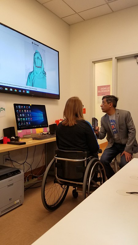
The progression of our ideas came to fruition this week as we heavily began idealizing and seeing how all of the parts of our design come together. The first half of this week’s class was allotted to learning 3D scanning from Ariel utilizing a handheld model. We then proceeded to scan our heads as well however, we learned that the scanner does not like dark surfaces and so we had to scan black hair with a phone light.

20170403_144847

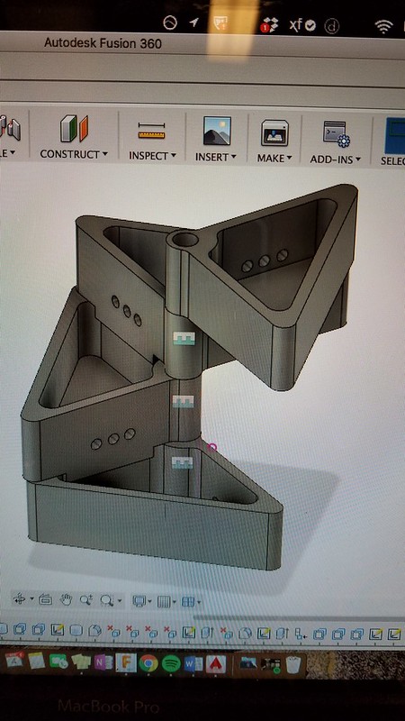
The next half of class we were heavily involved in redefining our project’s components with an initial rough print. This taught us that we need to prototype fast and quickly due to the nature of how 3D printing is not perfect and it is a reiterative process in order to perfect a design. We continuously developed our design and got an idea of how to make these modules separate in the case if we want to add more or less at any given time. The Fusion 360 model below shows how we visualized our final product.

IMG1740895582

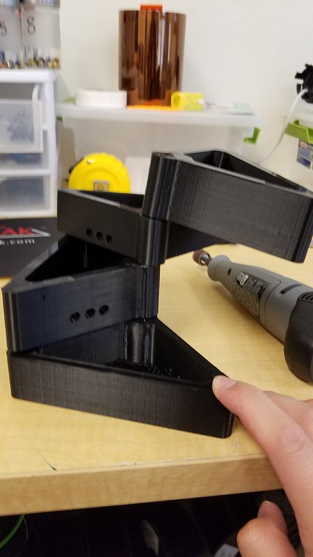
However, once we started printing, the holes did not line up correctly and sometimes the printer was having trouble with misalignment or if the filament ran out mid print as that happened to our initial prints.

20170405_150355

Then after another run through the printer we were able to narrow down the problems, address it and throw in another print. This one proved to be a much more successful model but it still did not stand up on its own which was cause for concern for us since we need it to be able to not only support its own weight but it needs to support, clay rocks, plants and moving water.

20170405_154052

Upon doing further research we found a great resource named “The Aquaponics Source” and it helped narrow down what type of plants, planting media as well as the conditions that are needed to keep our plants happy and healthy.

The next stages that I determined to be instrumental for the project is constructing the actual tank from 1/4″ acrylic sheets from the FabLab but they only had 1 clear one left and that was not enough since they were only 12″ x 24″ and so they are in the process of ordering more and it will come in about 10 days, which will hopefully give us time to cure and test our product. But I was able to use that one sheet and start dimensioning and designing the tank.

20170405_171649

20170405_173155

Our next step is to wait for all of the components we ordered to get here on time, which is the fish pump, tubing, finish printing the modules, as well as waiting for the acrylic to arrive and slowly put it together.


Where 3D Printing Meets Opensource Electronics

<spaOur world is changing rapidly with the Maker Movement setting its roots into modern society today. People are becoming more inclined to build and make their own personalized products rather than the general off the factory line model of the products that they seek. For instance, why buy a paper weight when you could 3D print your personalized model quicker and cheaper? But the same thing can be said about open source electronic projects such as using Arduinos and Raspberry Pis (Microcontrollers and Microprocessors). People are becoming bored with the fixed flow of technology development that they are creating their own electronic projects and devices. We came across a great example of this from the time that Mike Bohlman came in and told us about his endeavors in making. He had come across a space-based board game but became bored with it and created his very ow nmore interesting and interactive version included using electronics to make the board spots blink. You can find this project on his website called the Star Wars Armada Correllian Conflict. But the key way he did this was by providing the functionality using arduinos and presenting it in housing using 3D printing and supplies. This is also the trend when creating a product where Arduinos are used to add functionality, features, automated processes, interactiveness. While 3D printing is used to provide structure, casing/housing, internal frame to hold up components, physical hold/grip for user, fitting the electronics to the specific use size and shape wise, outer appearance and so on. These all tie in and make products what they are. These all blend into where 3D printing meets arduinos and micro controller. Highlighting this and allowing you to see this is the goal of this post. The most common application of these is the use of them to create DIY bots, droids, automated machines or parts and so on.

This has caught the attention of large companies where they see the potential for 3D printing for low cost production. Especially in areas for consumer products where there is huge reliance on these two prototyping methods, and they use these added effects/uses for these prototyping methods to have specific effects on users to create a new experience or to have a certain feel.

This cross between 3D printing and electronics is very feasible and has sparked the concept of 3D printing electronics already embedded in the product. Which would in turn, cut down manufacturing time of products that possess both components. This would be the most effective in creating whole electronic products at once. And this might be able to revolutionize the world and allow people to 3d print whole products from their home. More info can be found here. This article explains the power of combining 3D printed parts and electronics and the way the world is moving to combine them into 3D printable electronics.

Kickstarting the Prototyping Process

This class session focused on finalizing our project ideas and delving into the rapid prototyping phase of the project.

Ultimately, after weighing a handful of options, Team MakerLax chose to begin creating a prototype for a tie knot helper. Essentially, what this product does is allow users to tie a tie on-the-go, with little hassle. We believe this idea is useful for four main reasons. It is narrow in scope, with the tie helper serving a singular purpose and not attempting to accomplish a variety of tasks. It is relevant to our current environment, as the majority of college freshmen that we have surveyed have little-to-no knowledge on the intricacies of tie knots. It is convenient, with the ability to be used in virtually any environment. Finally, it is feasible and holds a competitive advantage over utilizing other forms of education, such as YouTube videos. While how-to videos are effective in some cases, they do not offer the physical presence offered by our product, nor can they be used while running to an interview.

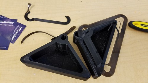
Above are the two initial designs we created, both composed of cardboard. While the one on the right offers more guidance, the one on the left can be easier to detach once the knot has been tied. One of the primary challenges associated with a product like this is being able to reuse the template, which requires the user to have the ability to remove the product once the tie has been finished. In order to do this, our next step is to prototype a metal using a flexible plastic filament, that can be bent or maneuvered in such a way as to be removed as the final step. The other idea we developed was to give the product the ability to be folded into smaller pieces, similar to many of the designs we have seen in the MakerLab. This would require more advanced engineering and design of the product within Fusion360, however we believe that it will ultimately benefit the user in the long run, as the template will be able to fold and fit into a suit pocket or a briefcase on the way to a meeting. Next week, we plan on printing a few plastic prototypes that will allow us to determine the true feasibility of the design, as well as potentially offering other ideas to incorporate into the product. Ultimately, we hope to decide on a final design so that we may begin finalizing the project details.

Final Project: Prototyping The MakerLab Bot (Team Xerott)

This session in class was one of the most productive where we got to start rapid prototyping our project.

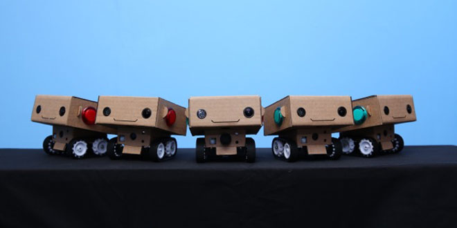
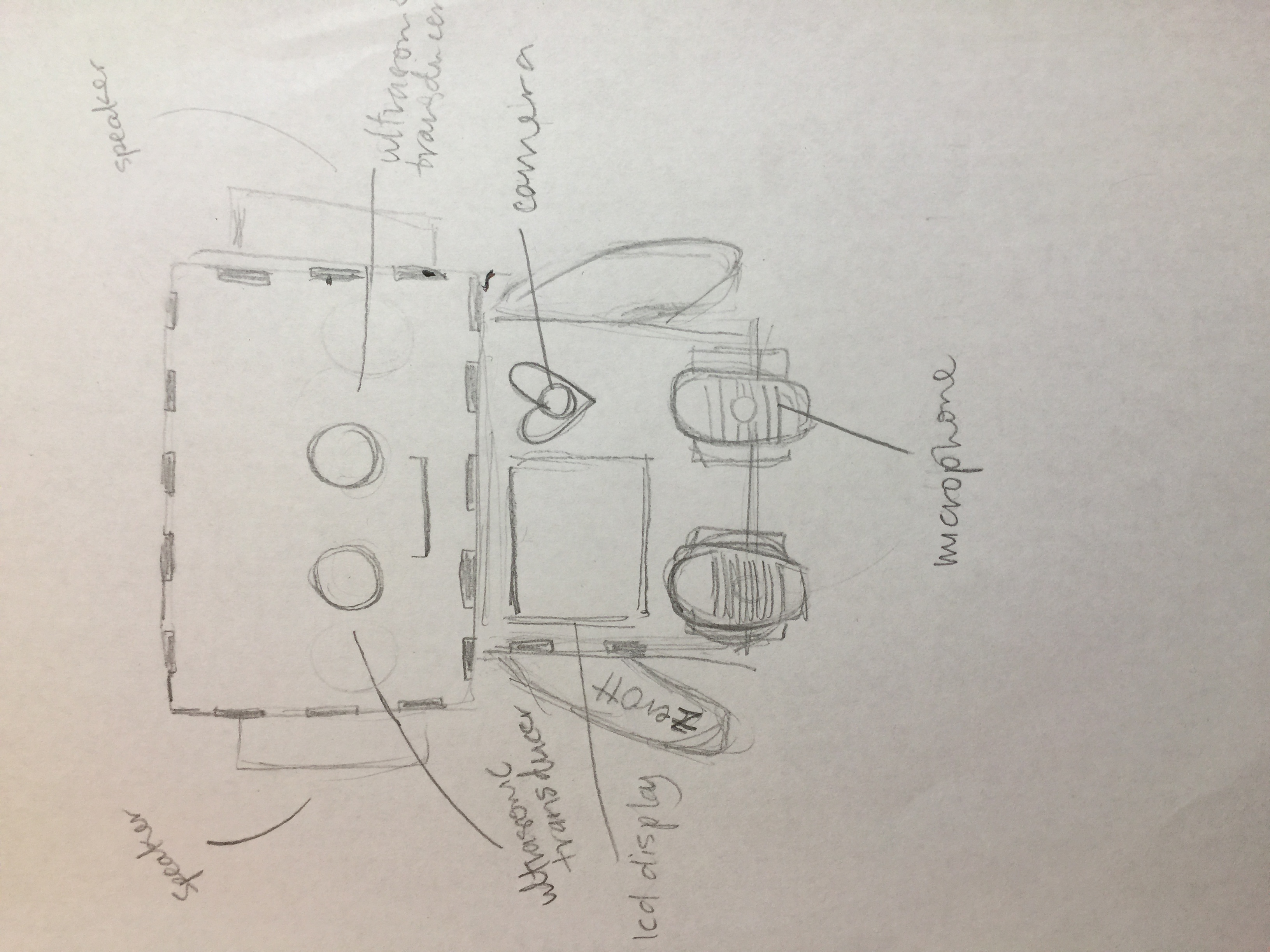
Team Xerott will create a the approachable Maker Lab bot that records people’s ideas and stories or any feedback they have for the lab. The bot will also have the ability to sense when someone gets close to greet the person. The video/audio recorded by the Maker Lab bot will be saved to an SD card/USB which could help in keeping a record of the things that are going on in the lab as well as collecting data for future use. This will help create interactivity within the lab and help with sharing what goes on in the lab to the world.

32964103794_05e060115b

Concept art for MakerLab Bot

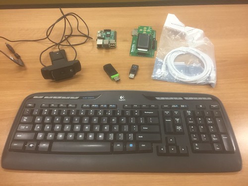
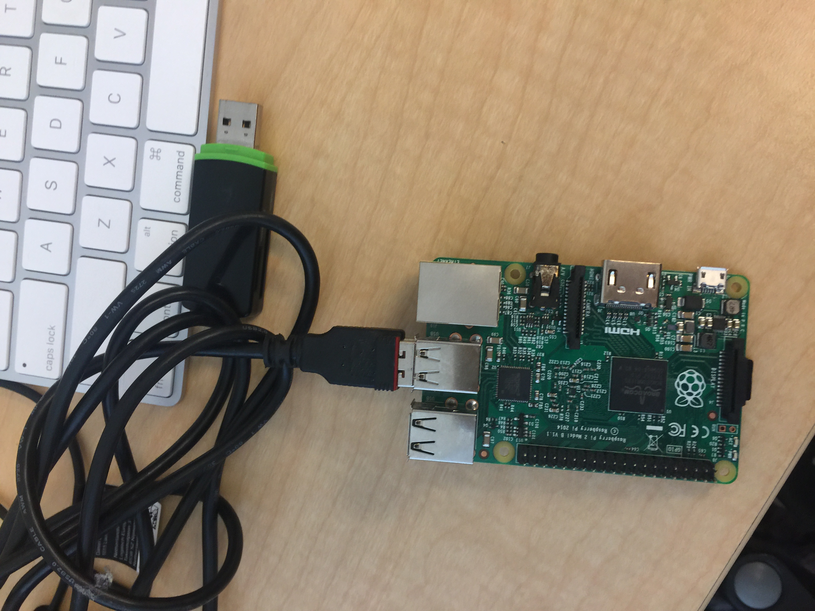
We obtained most of the parts needed to setup the Raspberry components included in the pictures below. And 3D printed the internal parts of the bot that will hold these components up.

IMG_0012

Components to setup the Raspberry Pi

IMG_0014

3D Printed internal frame

IMG_0013

Raspberry Pi Components

Key components of the initial solution:

-raspberry pi 3 board: to run the code

-jumper cables: to connect components

-mini (USB) microphone: to record audio and take in user commands
-camera module: to record the video
-speakers: to play tones, commands, and responses
-ultrasonic transducer: to sense the distance to the user to determine when to activate
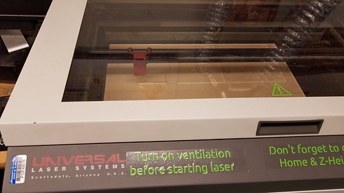
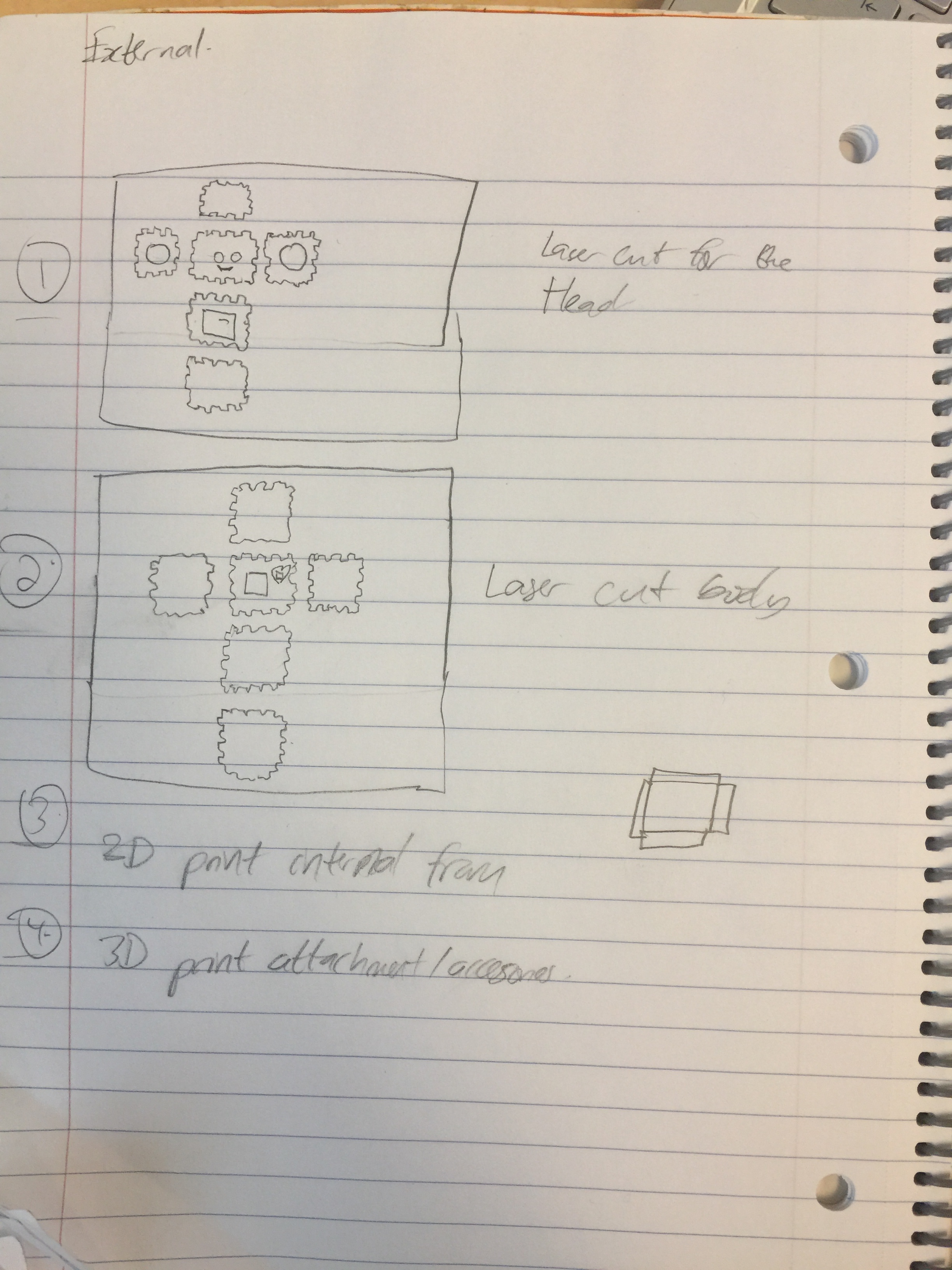
-laser cut inner frame (Wood or Cardboard): to hold up the internal components mentioned above.
-3D printed outer frame/attachments: to house the internal components and add aesthetic appeal (cute factor)

-LCD Display: to display image/message and possibly the recorded videos.

-Wheels and servo motors: If we get the project done ahead of time we will add this to make the droid mobile.

Our next step will be to start on the laser cutting of the outside portion of the bot as well as the coding which might be the most difficult part. But we will have the help of Youtube tutorials and the FabLab.  Looking forward to much progress next week.

Link to BlabDroid: http://blabdroid.com/ (Links to an external site.)

Link to Vishal’s demo: https://ibmtjbot.github.io (Links to an external site.)

 (Links to an external site.)

Link to hour long YouTube tutorial video we found: https://www.youtube.com/watch?v=e8gc7eGTtaw (Links to an external site.)

More than meets the eye

Design. A word that may be daunting to some and may be invigorating to others. Every aspect of our daily lives, from the food we eat to the products we use every day, have been thoroughly thought about and crafted to fulfill the epitome of its purpose. The stages in which a product comes to fruition are very extensive and is comprised of thousands of hours, dollars and a lot of people coming together for the common goal of solving a problem. The design process that I will talk about today will be focused on problems, from identifying them all the way to testing with users. It is extremely important to address a NEED first before coming up with a solution because if there is no one that needs to use it, then no one would want it.

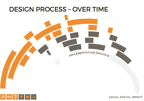
This is where I have seen people in BADM 395 fail quick and then have to start from scratch, it is creating a solution before thinking of the problem you are trying to solve. Human-centered design thinking is exactly as it sounds, by thinking of the humans that the product is intended for, then can you truly create something that is worth other people’s time, money and effort in utilizing the product. The design thinking process will help you be able to approach a problem you see in the community and create a product that will enable you to make it meaningful and to fully fulfill its purpose through iterations and critiques. The idea of this is to start thinking outside the box and sometimes take a few steps back in order to create the best of the best. The following steps outline how the Design for America human-centered design thinking process has been helpful for students all over the country.

Screen Shot 2017-04-02 at 10.58.45 PM

Step 1. Identify
Goal: Defining targeted problem spaces you will tackle to focus future research. This is a crucial step in creating something that will create the largest impact in the community. In order to build something, there has to be a need and identifying it is the first step. You want to be able to take large challenges and break them into smaller parts that are easier to manage and tackle. The issue of campus safety, for example, is very large, but you can examine it by looking at safety in classrooms, on the sidewalks or even in dorms. By analyzing assumptions and initial knowledge, you can see what knowledge you are lacking and where to find it. Think of the local organizations and mentors that are available to help you with this challenging area as well. For the example above, the police department and campus security may be helpful resources.

Step 2: Immerse
The next step is to be able to immerse yourself into your targeted audience. To empathize with stakeholders and uncover insights to deeply understand your problem spaces. The idea is to fully wrap your head around the problem space from every aspect and every party involved. For the example above, the idea is to talk to students, police, and people in the community that are potentially at risk from criminals or even feel unsafe in their areas. This will give you a much more well-rounded idea of identifying common themes, stories, and existing solutions. The UIUC Makerlab, for example, has the extremely expensive equipment and so talking to people in their and how they keep it safe would be helpful too.

Step 3: Reframe
The goal of reframing is to define the change you want to make in the world and determine what your solution needs to accomplish to get there. This is to define desired qualities as well as narrow down your focus. This also allows you to take a step back and gauge how you define a successful impact. As it pertains to BADM 395, the idea of reframing means that the product you create will ultimately solve your problem in an efficient manner.

Step 4: Ideate
This is another important step, brainstorming and generating a variety of ways that make  an impact and exploring alternative solutions is extremely important. Some students jump directly to this step and that is where they falter since they do not know what existing solutions may be out there. Thinking of any idea, no matter how big or small means that there is room for innovative ones as well as the possibility of ideas colliding and collaborating together.

Step 5: Build
Making a variety of tangible prototypes to communicate and test your ideas will allow you to see where your design falters and where it can be heavily improved. Without many iterations and samples, one can never perfect a product. Take the David Kelley example of the Apple mouse, for example, he tested and built hundreds of mouses in order to find what was wrong with each version and how to make it better. Getting started with low fidelity prototypes lets you envision your product and lets you fix potential problems quickly before they arise and cause more problems down the line.

Step 6: Test
Getting feeback to uncover insights and develop the nextsteps to improve a solution and product is extremely important. Being able to take this product into the homes and talk to the potential users is important since it allows your target audience to actually see a tangible product and envision if they can see themselves using it. This also allows you to obtain expert input and quotes about the solution to give you a much deeper and well-rounded way to go about the product. Testing a product in the BADM 395 course before it comes to fruition is important since we have to present it at the end of the year to our fellow classmates. This means that ensuring the product works for its intended purpose is extremely important.

To wrap up the design process, you have to keep in mind that these steps are not a one-way road, it is extremely important to constantly go back and forth to make corrections and improve designs with reiterations and consulting the users constnatly. By involving experts and professors in your process of creating the BADM 395 product, you will gain a deeper understanding and identify where and how you can fix it, so your initial idea becomes alive and ready to change the world.

Screen Shot 2017-04-02 at 10.58.53 PM

Resources

Week 9: Progress through Prototyping

This week our class split up into our individual project teams to start working on our initial sketches and/or first prototypes. If necessary, teams worked with CAD to design necessary parts to print.

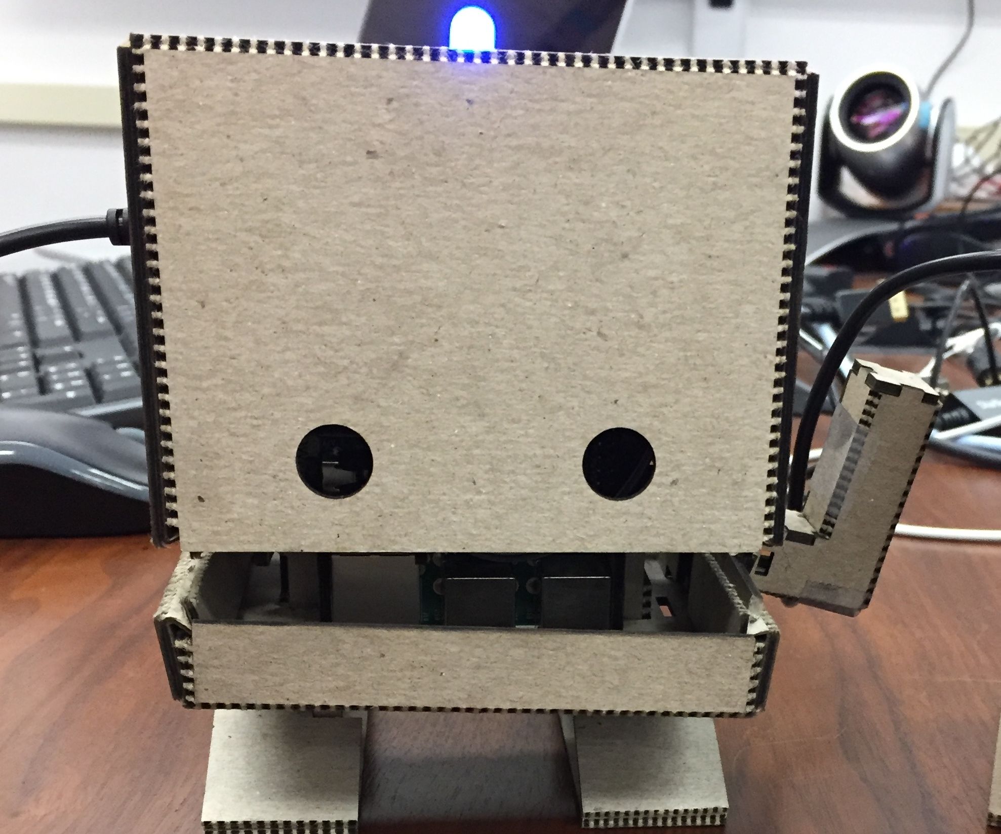
Our team decided to create a bot and after multiple discussions and sessions of brainstorming, we wanted the bot to be used at MakerLab to record a person’s idea/story/feedback. The goal for our bot is for it to capture that as feedback for future improvement of the MakerLab and also for publication of these stories. Our bot will mostly likely be triggered by a push of a button (sensors if we have enough time) that will start a series of different actions that will enable it to serve its purpose. Our bot comes from several ideas, including the blab droid, as well as the TJBot.


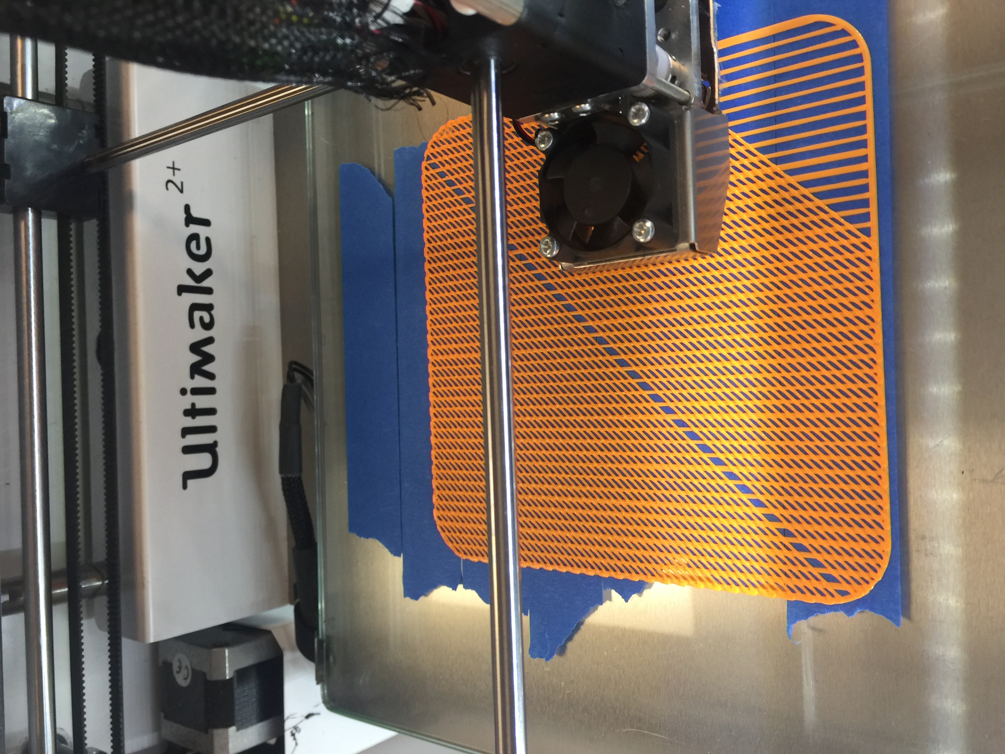
Our team had already worked on initial sketches that were already quite detailed. We also already had the design needed for the parts that needed to be 3D printed (blueprints and design from the TJBot). So we were able to start printing out the inside parts for our prototype (possibly will be used in our future). We have already started looking for our needed parts and have acquired some of what we need (Raspberry Pi), LED display, camera, SD card for the Raspberry Pi. We do still need to figure out what type of materials we want for the outer structure of our bot.

Our team, this coming week will need to go to the FabLab to figure out the dimensions of our bot, as well as the how the laser cutting design will work out. Taofik has been playing around with the coding of the bot, while Tiffany and I have been figuring out the logistics of the design and how we’ll go through with the design (as well as the material needed).

I’ve learned this week that prototypes do not and should not be perfect. The more flaws and imperfections your prototypes have, the better it will be and have the potential to be better. Prototypes should continue to change and give the creator an opportunity to make a better product.

How to get “Perfect” Prints

One of the best features of consumer 3D printers is their ease of use. All the user needs is to slice their model with their desired settings and upload it to the printer via a USB cable, flash drive, etc. While this is straightforward, there are quite a few intricacies to the process. Slicing a 3D model with “perfect” settings does not necessarily lead to a perfect print. There are a plethora of discerning factors and principles of additive manufacturing that can skew the results. These problems are usually grouped into 3 categories: material  issues, software, and hardware. User error can sometimes come into play, but that also usually falls into one of these three mentioned. 3D printing as it is now is not a perfect science, there are many issues prevalent within the technology that prevent it from being greater than what it already is. The slightest mishap during or even before a print begins can cause it to fail or lower in quality. Sometimes, prints even fail for seemingly no reason, and the failed print is simply a one-time occurrence. We can, however, take measures to ensure that we can get the best quality out of our machines as possible. As 3D printing is still rapidly evolving, there really is no “perfect” print. We can get very high quality parts created, but as it stands now there is always something that can be improved in a print. This post is meant to serve as a universal guideline/checklist for getting the best quality prints out of your 3D printer as possible.

1. Filament:

There are a variety of printing materials out there, with the 2 most popular being ABS and  PLA. Other types are special exceptions but they usually have the same conditions for printing as one of these two. You should choose what type of filament to use based on what your part requires. Each has its trade-offs.

ABS- Relatively strong with a little bit of flex. Good for parts that will be used a lot, or pieces that you don’t necessarily care how they look. However, it is NOT food-safe, and somewhat difficult to print. It requires a heated printed, and sometimes a little bit of glue on the surface to help with adhesion. It also has a very strong odor so you need a well-ventilated area.

PLA- Probably the most common material used today. It is vegetable-based and is easier to print than ABS. It also tends to look nicer and the prints are more clean coming out. However, it is much more fragile and sensitive to temperature. Therefore, this is good for models that won’t be used heavily and are more for display.

More in-depth info on filaments here: https://pinshape.com/blog/popular-3d-printing-filaments-3d-printer-filament-types/

2. Software

When slicing your file in your slicer, you have a variety of options. Different combinations produces different results, however, these can vary widely depending on the software and the printer, as well as the filament. An important consideration before printing is what kind of software you are using and if it works properly with your printer. Some companies produce their own proprietary software that can only be used with their printers and vie-verse. This makes it easier for users, but in most situations this actually limits the options. They are many other non-locked slicing softwares that can be used with any printer, but not all printers can use any software. Sometimes you will simply have to test these for yourself and see what is compatible with your printer. These are the more common options adjusted by users.

Layer Height- How tall the layers of the filament are in the z-axis(upwards direction). Usually ranges from .1 mm to .4 mm. The finer the layers, the higher quality the print will be.
Comparison of 4 different layer heights (finest to roughest from left to right)

Infill- How dense the object printed will be, ranging from completely hollow(0 %) to completely solid (100%). Note that as you get higher and higher in percentages, the difference starts to become less noticeable. The shape of the infill is usually also adjustable, these include hexagonal, rectilinear, or even custom settings.
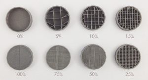
Examples of different infill percentages
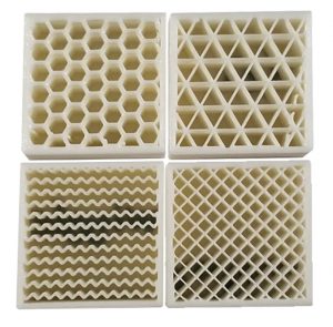
Different infill types

Shells/Perimeter- The number of outer lines the printer will produce on the perimeter of the print. The standard is two. This affects the strength of the print.

Speed- How fast the print nozzle will move during the printing process. Higher speeds give faster prints, but lower quality, while the reverse is for lower speeds.

Supports- If your print has overhangs, depending on the angle, the printer may attempt to build the layers over nothing, causing a drooping effect. To compensate, supports (layers thinner than usual), are created by the printer which can be broken off or in some cases dissolved later. The density of the supports can usually be adjusted as well. Flimsy supports break away easily, but may also be torn away accidentally by the extruder during printing, while more rigid supports are can hold more reliably but are harder to remove.
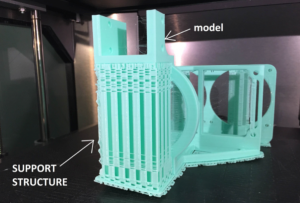
A model with support material

Raft/Skirt/Brim- The more surface contact that your print has, the better it will adhere to the printed during printing. If it has little surface area, there is a possibility that it will actually peel off the printer. In these cases you may want to use a raft, skirt, or brim. There are all similar but each has a specific use. The raft is the most generic and is like support structure but is only composed of a few layers that the model is printed on top of. It is used to provide a larger “footprint” for the model and is removed like support material. Take note however, that the bottom of the print is usually affected by this, as it will tend to be more rough having been printed on top of more material rather than the print bed. A skirt is like and outline of the print made around it. This is to ensure that the filament is flowing properly before the actual print begins. A brim is like a raft, except the bottom layer is printed with the brim instead of on top of it. It provides stability to prints with small contact points, and can be removed or kept on after printing. More info on all of these here https://www.simplify3d.com/support/articles/rafts-skirts-and-brims/

Temperature- Both the temperature of the extruder and the buildplate of the printer can be adjusted in most slicers. The temperature of the extruder and bed should be adjusted depending on the type of filament that you are using. Most filaments come with a suggested nozzle and build plate temperature. Sometimes, the bed may not even need to be heated. Printers also come with fans for the purpose of cooling the components and/or the filament itself. Slowing down or speeding up the fans will affect the flow rate of the filament as well as the quality of the print. This usually doesn’t need to be adjusted but feel free to experiment.
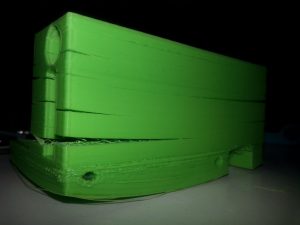
Warped bottom and split layers due to poor adhesion and/or temperature settings
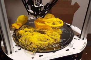
If you need a heated bed make sure it stays on

Retraction Rate- Since the filament in the extruder is under constant heat, it will always want to flow out of the extruder. As the nozzle moves about, small bits of filament may be extruded unintentionally. The retraction setting allows the filament to be withdrawn back to prevent this from happening. Too little a retraction rate will cause strings, while too great may actually wind the filament out of the extruder. Once again, a setting that may some testing to find what works best, it also depends on the filament used as well as the temperature.
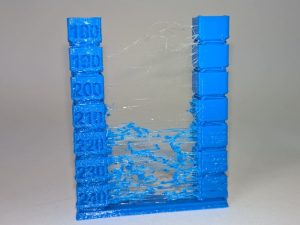
An example of too low a retraction rate

There are more settings than those listed, but these are usually the ones that affect print quality the most. Another factor that can affect prints is random bugs in software or issues in the actual model that affect slicing. This is why you should always review your model after it has been sliced in your slicer software before uploading it to the printer. Some slicers have their own file repair settings, but online repair services can be good as well. https://makeprintable.com  https://tools3d.azurewebsites.net
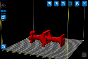
File loaded into software before slicing
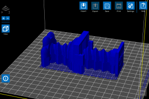
Sliced file output, note the large block in the center of the model that was not present in the original

3. Hardware

3D printers, like all machines, can and will eventually fail and usually require maintenance. You don’t necessarily have to take your printer apart bit by bit, but you definitely need to check on your printer and its components every now and then to ensure every things is fully functional. If desired, you can also upgrade your printer parts with purchasable upgrades, or even print add-ons that will improve print quality.

Extruder- The integral part of the printer responsible for the actual printing. A user needs to make certain that this piece is fully functional and taken care of, otherwise no printing can occur. Taking care of your extruder is relatively simple. Just make sure that it is not overworked and kept clean. Prints that run for hours are fine, but you definitely you should not have your printer running 24/7. After a long print maybe give it a break for a few hours or so. Make sure to exercise proper fan usage. It is wise to have at least one, if not even 2 fans running on the extruder during prints. This improves print quality and extends the lifetime of the component. Also, whenever possible make sure to allow your fan to cool off your extruder instead of just turning the printer off. By allowing the fans to run after a print, the extruder can cool properly and gradually unit the next print. Overheating can cause filament to stop flowing entirely and damage the extruder, so be wary of this. It is also a good idea to maybe open up your extruder whenever you see an issue in printing or just feel like it’s time to clean it. When attempting cleaning, a wire brush is usually the go-to tool as most if not all extruder nozzles are made of metals like brass.
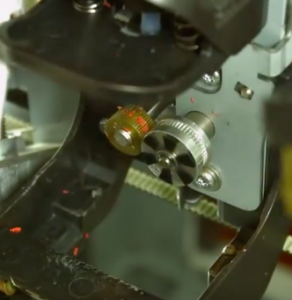
Bits of filament stuck in the drive gears of the extruder can really cause printing problems
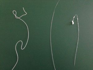
Signs of extruder problems. The left filament strand is fine, while the center is too thin and the rightmost is too “globby”
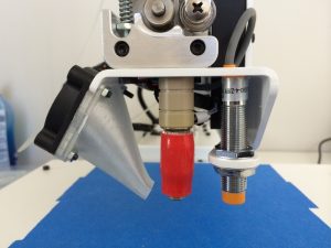
A 3D-printed fan mount made by the printer for itself to improve quality

Build plate- Maintaining the integrity of the build platform is key to ensuring good prints. While they can be fixed/replaced like extruders, they are usually much more difficult to do so. One of the most important aspects to look out for is leveling, as in keeping a proper distance between the extruder nozzle and the build surface. Too far and the filament will not stick; too close and the filament will have no room to exit the nozzle and the bed may be damaged. Most printers come with instructions on how to properly level the bed, and some even have auto-leveling settings. Manual offsets can also be input if desired. Like the extruder, it is important to keep the bed clean, as residue from prints and glue for adhesion if used, can buildup overtime and harm the surface as well as your prints. One method of preventing this is using painter’s tape. By applying it over the build plate, you can provide a surface that in some cases is actually better for adhesion than the actual platform, as well as easily peel off the prints afterwards. It also assists in protecting the bed. Many printers also come with beds made from glass, which must be taken care of with caution, as overheating or mishandling of the printer can damage the bed severely and become a safety hazard.
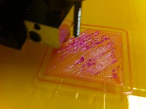
Sign that the bed is adjusted too close to the extruder
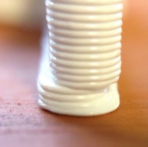
A print with an offset shift due to a loose build plate
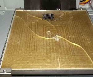
Chipped and cracked glass bed, most likely occurred when trying to remove a print

Motors- In order to drive the axes of the printer’s nozzle and bed, stepper motors are used. One motor is used for each axis(X, Y, and Z), and the extruder and bed can either share all three, or one may posses all of them (in which case that respective part would be the only one moving). These motors are what allow 3D printing to be 3D. Most use tension belts or rods to move the extruder and/or bed. This motors don’t require as much maintenance and checking as the nozzle or bed, but it is certainly a good idea to check on them and perhaps regrease them every now and then. You may also want to check the wiring on the motors, as the repeated motion of moving back and forth can actually break them and sometimes even get caught in the gears, effectively ruining the printer. Unless you’re experienced in electronics, this can be difficult to fix. Taking good care of your motors can not only save you from buying new ones later, but also improve print quality. Everyone can agree that the smoother a print is, the better it looks and the higher quality it is. The accuracy of the prints depend on the stability of the motors. If they are too tight or too loose, your prints will suffer.

A stepper motor with a loosened belt

A print with ridging along the z-axis, a sign of wobbling motors