Kickstarting the Prototyping Process

This class session focused on finalizing our project ideas and delving into the rapid prototyping phase of the project.

Ultimately, after weighing a handful of options, Team MakerLax chose to begin creating a prototype for a tie knot helper. Essentially, what this product does is allow users to tie a tie on-the-go, with little hassle. We believe this idea is useful for four main reasons. It is narrow in scope, with the tie helper serving a singular purpose and not attempting to accomplish a variety of tasks. It is relevant to our current environment, as the majority of college freshmen that we have surveyed have little-to-no knowledge on the intricacies of tie knots. It is convenient, with the ability to be used in virtually any environment. Finally, it is feasible and holds a competitive advantage over utilizing other forms of education, such as YouTube videos. While how-to videos are effective in some cases, they do not offer the physical presence offered by our product, nor can they be used while running to an interview.

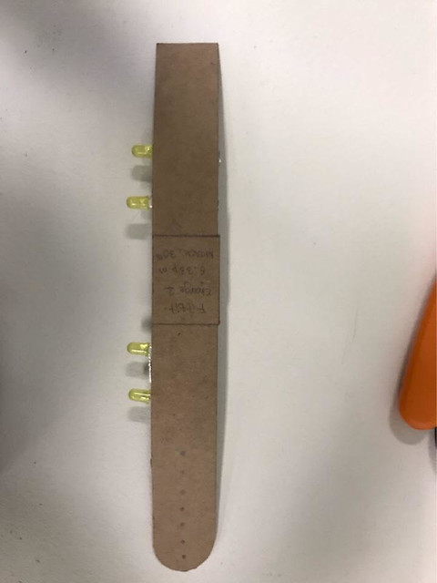
Above are the two initial designs we created, both composed of cardboard. While the one on the right offers more guidance, the one on the left can be easier to detach once the knot has been tied. One of the primary challenges associated with a product like this is being able to reuse the template, which requires the user to have the ability to remove the product once the tie has been finished. In order to do this, our next step is to prototype a metal using a flexible plastic filament, that can be bent or maneuvered in such a way as to be removed as the final step. The other idea we developed was to give the product the ability to be folded into smaller pieces, similar to many of the designs we have seen in the MakerLab. This would require more advanced engineering and design of the product within Fusion360, however we believe that it will ultimately benefit the user in the long run, as the template will be able to fold and fit into a suit pocket or a briefcase on the way to a meeting. Next week, we plan on printing a few plastic prototypes that will allow us to determine the true feasibility of the design, as well as potentially offering other ideas to incorporate into the product. Ultimately, we hope to decide on a final design so that we may begin finalizing the project details.

Be Bold & Just Do It

The time flies so fast! We only have one month before ending this semester. Now, it is time for us to utilize what we have learnt in the first half of the semester and realize our ideas with the power of 3D printing. I am in the team XNihilo. We plan to design a fitbit wristband attachment that can detect hydration levels from the skin. When the user dehydrates too much, the wristband attachment could flash to remind the user to drink water.

Yes, it sounds complicated and none of us has much engineering background. However, with the support from the Fab lab, we want to do our best to see whether we can make it.

33764942846_5b9e601c26_o

At the very beginning, we thought that we need to use a humidity sensor that is compatible with the Arduino platform. Thus, we did a substantial amount of online research and found some promising sensors. One of the sensors I found is DHT 11. DHT 11 is an ideal sensor for our project because it can precisely detect the hydration level of the skin and the size is small enough to be installed on a wristband. Then, we went to the Fab lab to check whether we could get DHT 11 or other similar hydration sensor directly from the lab.

DHT11

We met Brandon at the Fab lab and explained our idea to him. To our surprise, Brandon mentioned that we might not need to use the humidity sensor if we only wanted to detect the hydration level of the skin. We could use a very simple circuit to test the resistance on the skin. If the skin was wet, then the resistance should be lower; if the skin was dry, the resistance should be higher. Comparing the size of a humidity sensor to a simple circuit, we decided to try the circuit first. If it did not work, we could still use the humidity sensor.

33805389495_93a7f3c349_o

After we determined the solution of how to detect the humidity level of the skin, we needed to set up a proper distance between the positive and negative coil we placed on the skin. If the distance was too large, the sensor would not be precise enough; if the distance was too small, the resistance would always be low. Therefore, it was time to do a scientific experiment. We wrote down four distance that we wanted to test. As you can see from the picture below, the distance are 15, 10, 5, 2 mm. Then, we placed the coils based on the distance we set up on Ana’s arm. We connected the coil to the circuit one by one and we selected four most frequent numbers displayed on the screen.


Data Set
SD
Skin 1 331 327 329 317 6.218253
Skin 2 295 288 277 286 7.416198
Skin 3 354 323 321 317 17.01715
Skin 4 318 315 317 310 3.559026

1


33764943536_851979898d_o

Because we want to select the distance that can work stably, we calculated the standard deviation of the data we collected. The SD of distance Four(2mm) was the smallest, so we chose 2 mm distance for our humidity sensor simulation circuit. To give our classmates and professor Vishal an idea of what we would make, we did a super simple prototype, a cardboard warp. In this upcoming week, we plan to use the 3D printer to make a solid wrap and improve our circuit.


33764942566_8eb853f4d4_o

Week 9: Crude Prototype

This week is where we put together the culmination of our new found maker knowledge. We are to finally design the dehydration wristband fit bit attachment. In class, we had 3 hours  to work on prototypes, create initial crude prototypes or detailed sketches, start work on any CAD design required, create Final Bill of materials/order or source any parts required, establish contact with any human resource required for the project, finalize information resources for the project, and review work allocations among team members.

We had definitely found research to prove the feasibility of our project in the weeks prior and we also know that people have created an extremely accurate hydration sensor before according to this article. Although we knew that this technology existed, we weren’t able to find the same sensor for sale. So we looked and found a sensor for moisture and heat online. Our next issue was designing the band and having all of our materials fit in one small space. We had known that we would be using Arduinos for our project but we had only seen the larger Arduinos that would not it on our band. With more research, we found out that there were smaller Arduinos that we could utilize. We discovered that we could use either a micro Arduino or a Lilypad which could work better on fabrics. We wanted to know which of these would be the best option for our design. To figure out what other materials we needed for our design, we took a trip to the CU FabLab to see what they could offer us in terms of materials and design advice.


Us on our way to the CU FabLab

on our way

CU Fab Lab in the Distance

fab


Arriving at the FabLab we were greeted with some familiar faces ready to help us figure out hat our projects need. We approached Brandon, who was an ECE major and led the programming workshop for our class, he took interest in our project and agreed to be our contact and resource for this project. Brandon explained that they did have a lot of the materials which we need for the project. He showed us how small Arduinos can be and how they can fit on the Fitbit Charge 2 that we were modeling it after. Furthermore, he told us that we can made a moisture sensor in the lab instead of ordering one online. We made plans to meet with him in the FabLab on Thursday to do some work on our prototype, sensor and the project as a whole. The worries that we had immediately vanished. We knew what materials we were going to use, what design we were going to use, what we were going to do when we meet and who would be responsible for each job on the project.

Size of the micro Arduino we would use compared to the FitBit wristband:

sxe

Here’s a summary of what we had decided on:

Materials: 3D printing filament, wires, LEDs, resistors, copper strips and a fitbit.

Jobs: Ana – coding and test subject, Ben – soldering and research, Anjali – Design on fusion. We also had all agreed to collaborate to get the project done in the FabLAb with Brandon and help each other out when help was needed.

Here’s a summary of what had happened after class on Monday:

Wednesday – Met up with Anjali at the MakerLab in the BIF to try to scan the current wristband attachment for Fitbit. We found out that it would just be easier to design the band as one long strip instead of two separate attachments and that designing on Fusion 360 would be easier than to scan the bands. We had found a downloadable link on Thingiverse for a Fitbit wristband attachment which we could edit to fit the Fitbit model which we had (Fitbit Charge 2)

Thursday – The whole team met up with Brandon at 5pm at the CU FabLab to work on our prototype for monday. We decided to use a cardboard material instead of the 3D wristband because we had not had time to edit and print the design we saw. However, during this meeting we had decided to solder some LEDs and wire and start testing out how we would like to create the moisture sensor with the copper strips. We measured out different distances  to see which would pick up the most activity. The strips on the ruler was our control because there should be no moisture on it, and my skin was the experimental factor.  We kept running some tests before time ran out and we went home. However, we at least had an idea of what we were going to do in the weeks going forward. In the next few weeks we plan to meet with Brian to figure out  how to put together the sensor and work on the design overall with the 3D printed wristband.


Here’s some visuals of our time in the Fablab:

Sensor we are modeling our moisture sensor after

origsensor

Control on ruler compared to skin

skin 2

skin

Skin Experiment

test2

Testing out the sensors

alsjd

test 3

Cardboard Prototype

proto

Time for Action

It was finally time to put our CADing, ideation and prototyping skills into action. Our group, JJJ inc, is designing a smart switch which can potentially pave way for cheaper smart homes and user customization. We started the class with watching a few videos on getting our spirits up and running. Before class our team had the general design concept in mind, in which we wanted to install a box on top of a light switch and have a motor move it up and down remotely, but we had not thought about the constraints of the functionality and in the design itself.

We then headed to the CU Fab lab to explore and get advise about our design and its functionality. One of the helpers at the fab lab suggested we use a rack and pinion arrangement to move our switch up and down. We then designed and discussed our idea among the team and came up with a simple working model which could be simply 3-D Printed. Our idea is to attach a motor to the Pinion Gear which is connected to a rack gear which moves linearly. The rack gear will have a hole in its center which will be mounted over the light switch.

Our next step was to CAD the rack and pinion using Fusion 360. We started of with first measuring the dimensions of the light switch to get an idea about how much the rack must move linearly to push the switch into position. We then used it to design the rack and pinion model which we now have put to print.

The next step of our creation is to design a housing for the rack and pinion and to integrate a Bluetooth module using an arduino uno. Later that week I spoke to one of my friends in the ECE department who suggested that the simplest way of operating a motor remotely will be using a Bluetooth HC/05-06 module which is available readily. I can already seeing our project come to life its just a matter of a few weeks!

This a step by step guide to anyone interested in working with Bluetooth modules on an Arduino Uno board : http://www.instructables.com/id/Arduino-Control-DC-Motor-via-Bluetooth/

Ready, Set, Make!

It’s hard to believe we have been away from the Maker Lab for over a month! Week 9 found us back in the Maker Lab after a week away for Spring Break and the previous 3 weeks away at the Champaign Urbana Community Fab Lab.   I think all of us were glad to be back “home.” This week we focused on design and prototyping as we start to bring our project ideas to life.

IMG_1468

One of the most important points we learned emphasized that design sketches and prototypes are by no means a final product. They can (and should be) rudimentary, use household items, and use temporary solutions. David Kelley, of IDEO, in this presentation says, “Design is an iterative process.” The quicker you can get feedback from a product, the more successful it will be. Each presentation allows you to get more feedback, and people will always tell you “everything that is wrong with it.” Kelley continues in this video to talk about the design of Apple’s mouse, and how a temporary prototype solution to keep dust off the optics can turn into a permanent part of the design. As you improve, you will quickly have a better prototype on your hands and you can even start using custom parts. Jeremy Losaw in “ProtoTYPING: Tips to Get Started on Your Product Idea” says “3D Printing is a great way to get custom parts quickly.” Luckily for us, we have access to the Maker Lab and Fab Lab to make those custom parts with the very talented staff in both labs.

IMG_1467

After going over all these discussion points, it was time for our groups to split up and start designing and prototyping. My team, BCC creations, settled on making a low cost security system to provide college students some peace of mind when they are away from their apartments. We have named our product “Security SMS” and will use motion detection to alert of unauthorized entry. When someone enters the apartment, they will have 10 seconds after the motion detector is tripped to turn off the alarm. Otherwise, an alarm will sound and a text message will be sent to the roommates living in the apartment. We will use a Raspberry Pi with Twilio to send the SMS, Piezo for the alarm, and an ultra sonic sensor for the motion detector. We will 3D Print the housing that will hold the alarm, which can be attached to a wall with Velcro. Originally we considered using a Bluetooth unit for the SMS function, but after I went to the Fab Lab during class, we decided to try Twilio.   Aakanksha at the Fab Lab offered to help us, and Charlene and I have friends studying Engineering that have offered their talent to us should we need it when programming. Our next step is to start working on putting together a circuit and programming the Raspberry Pi. When we know how big the circuit will be, then we can start prototyping the housing for 3D printing. Although it may be tricky to design in the software, we presume it will be an easier task that working with the technical specifications of the alarm. Regardless, with the three of us working together, we are all excited to prototype!