It was finally time to put our CADing, ideation and prototyping skills into action. Our group, JJJ inc, is designing a smart switch which can potentially pave way for cheaper smart homes and user customization. We started the class with watching a few videos on getting our spirits up and running. Before class our team had the general design concept in mind, in which we wanted to install a box on top of a light switch and have a motor move it up and down remotely, but we had not thought about the constraints of the functionality and in the design itself.

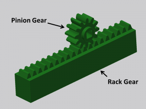
We then headed to the CU Fab lab to explore and get advise about our design and its functionality. One of the helpers at the fab lab suggested we use a rack and pinion arrangement to move our switch up and down. We then designed and discussed our idea among the team and came up with a simple working model which could be simply 3-D Printed. Our idea is to attach a motor to the Pinion Gear which is connected to a rack gear which moves linearly. The rack gear will have a hole in its center which will be mounted over the light switch.
Our next step was to CAD the rack and pinion using Fusion 360. We started of with first measuring the dimensions of the light switch to get an idea about how much the rack must move linearly to push the switch into position. We then used it to design the rack and pinion model which we now have put to print.
The next step of our creation is to design a housing for the rack and pinion and to integrate a Bluetooth module using an arduino uno. Later that week I spoke to one of my friends in the ECE department who suggested that the simplest way of operating a motor remotely will be using a Bluetooth HC/05-06 module which is available readily. I can already seeing our project come to life its just a matter of a few weeks!
This a step by step guide to anyone interested in working with Bluetooth modules on an Arduino Uno board : http://www.instructables.com/id/Arduino-Control-DC-Motor-via-Bluetooth/

