Navigation

This post is here for easy navigation of my work over the past few months. For individual posts, see below. For my full blogroll, see here.

Getting started, and miscellaneous posts

“Hello World”, the maker community world

Beauty in Equations

Ready steady GO (expiriences in learning Fusion 360 CAD)

Getting going, lets 3D print!

Tying up a few ends (miscellaneous side projects)

“How to… ” Join me on my skills series

How to… Laser Cutting
How to… Arduino
How to… Soldering 
How to… 3D Scanning
How to… Engrave Glasses (semester post)

“Time…” A semester project

Part 1: Time for a semester project? (this post)

Part 2: Progress through time

Part 3: Tick tock goes the clock

Part 4: What’s in a face?

Part 5: Closing Time

Closing Time

Part 1: Time for a semester project?

Part 2: Progress through time

Part 3: Tick tock goes the clock

Part 4: What’s in a face?

Part 5: Closing Time (this post)


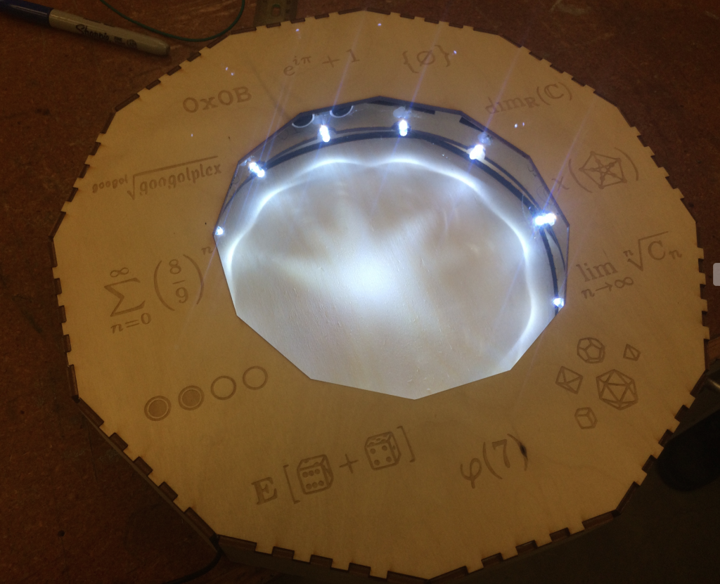
Rounding up my “time” posts, this is my final prototype for my project.

Here (below) is my final prototype functioning. You use your own hands as the clock hands, and the shadow cast by the LEDs tells the time. When the clock is not triggered, it acts as a light installation.


Heres how I’ve incorporated the different skills from the semester into my project:

  • Soldering: hours upon hours with the soldering iron putting together those LEDs, wires, and components.
  • 3D-Printing: printed gears for a mechanical clock idea (didnt make it onto final design). Designed on Creo after an unsuccessful attempt on Fusion360.
  • Laser Cutting: created an interlocking box enclosure to house all the components. Designed using inkscape.
  • Arduino: wrote code from scratch for the interactive nature of this clock.


For future iterations, things that i’d consider doing:

  • diffuse the LED light so that its a softer glow, maybe with a fabric covering
  • reset the time code at midnight so that theres no chance of it hitting problems from constant running
  • hinged lid for easier access to inside components, or better press fit box
  • overextend the lip or mount LEDs much further into box, so its not possible to look at them directly
  • the code could be rewritten to be more efficient
  • troubleshoot to ensure every single permutation is correct.
  • laser hole in top back for a nail to hang on a wall
  • determine optimal angle  to trigger the ultrasonic sensor.


(return to main navigation menu)

What’s in a face?

Design, ideas, progress, challenges, and workarounds for my semester project. Part 4 of 5

Part 1: Time for a semester project?

Part 2: Progress through time

Part 3: Tick tock goes the clock

Part 4: What’s in a face? (this post)

Part 5: Closing Time


With the functionality implemented on a working prototype, the last few stages are aesthetic.

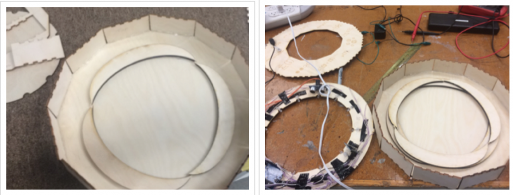
I designed the casing and enclosing structure to be in the style of a press-fit laser cut box. These are something that I really liked the look of and wanted to have a go at creating.

Screen Shot 2016-05-13 at 16.26.52

examples of press-fit boxes

.

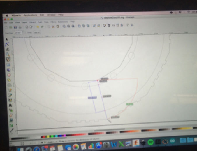
I designed it in the editing program Inkscape, and have made it out of 1/8” wood.

Screen Shot 2016-05-13 at 09.46.26

Hand drawing a box design. Hoping it will fit together!

Screen Shot 2016-05-13 at 16.15.45

laser cutting the design

Screen Shot 2016-05-13 at 16.16.19

putting the box together

I built in a platform to raise the level of the LEDs so that they would cast a general glow, instead of seeing point lights. (point lights are visible if it is mounted directly onto the base).

While the box does interlock, I didn’t design it to take into account the material that would be removed when the laser cuts, so it does not “press fit” together on its own. A glue gun fixes everything though.

On designing the clock face

Tying in with my equations, and “world fundamentals” theme, I wanted an equally relevant clock face.

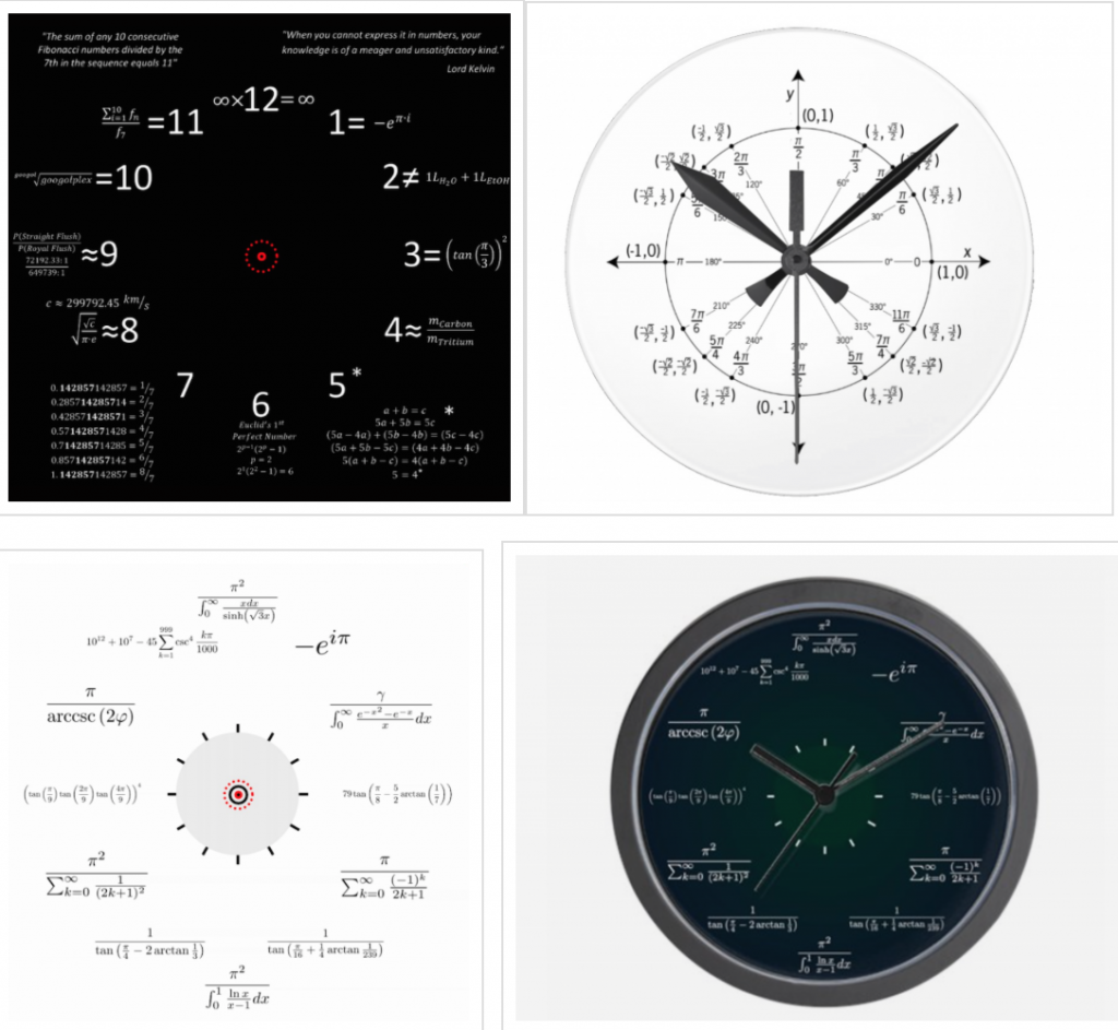
A lot of ideas that I came across involved using numbers that numerically evaluated to the clock face number:

Screen Shot 2016-05-13 at 16.21.28

clockface examples

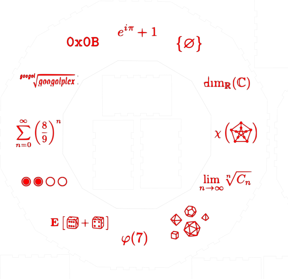
These were fun, but I wanted each number to have a deeper meaning. The result is a clock face where each number is relevant to a different mathmatical theorem. The majority of this clock face was found online.

Screen Shot 2016-05-13 at 16.22.31

My clock face

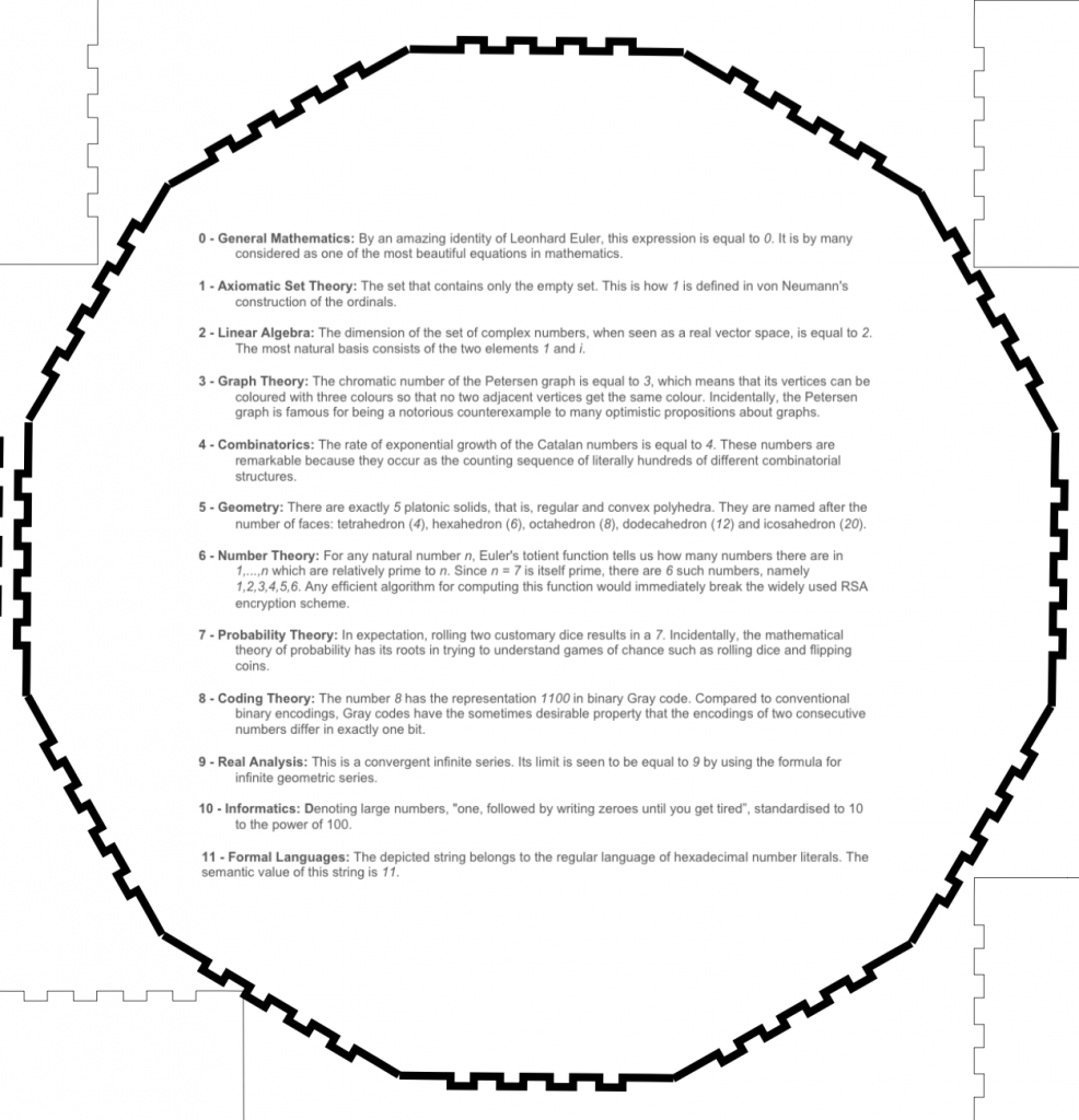
Each number is related to a theorem, if you’re curious…

Screen Shot 2016-05-13 at 16.24.31

I have this description rastered onto the back of the clock


Finally…

Screen Shot 2016-05-13 at 10.19.18

Ta daa!!


“I can run, but cannot walk. I sometimes sing, but never talk. I need your hands upon my face, for you to check me, to keep your pace”.


(return to main navigation menu)

Tick tock goes the clock

Design, ideas, progress, challenges, and workarounds for my semester project. Part 3 of 5.

Part 1: Time for a semester project?

Part 2: Progress through time

Part 3: Tick tock goes the clock (this post)

Part 4: What’s in a face?

Part 5: Closing Time


Prototype 2.

Simplifying circuits is how I’m going to fix things. Prototype 1 tried to incorporate 2 colours of LEDs, with only 12 IO points. Simplifying the design, I’m reverting to a single colour of LED, which does not call for the circuitry to be as complicated.

Screen Shot 2016-05-13 at 09.45.41

circuitry works! Just the code to rewrite now then.

The LEDs can light much brighter in this configuration, so i can have greater spacing in my clock face and go for a bigger frame.

Screen Shot 2016-05-13 at 10.20.01

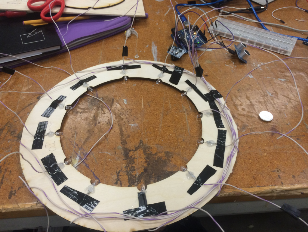
working on framework of prototype 2

Screen Shot 2016-05-13 at 10.20.17

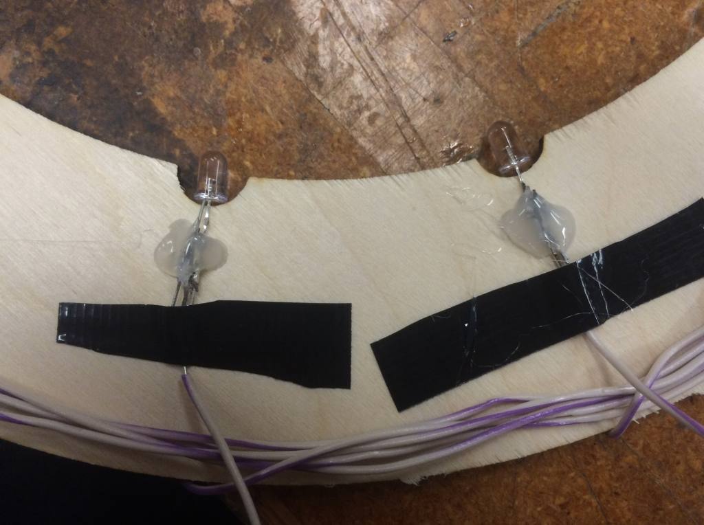
Detail of LED positioning

A little spanner in the works at this point: the time code stopped running on the device. With a lot of help and troubleshooting, the problem was located as a dodgy connection in the hardware, not a code issue as originally expected.

Coding shenanigans

Screen Shot 2016-05-13 at 16.41.21

Editing code

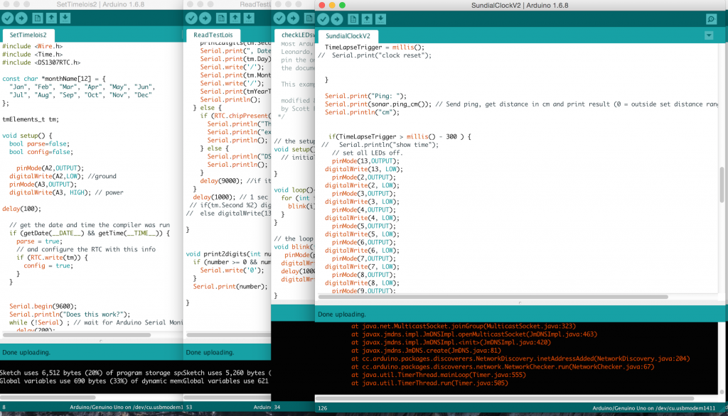
My code has also been through a series of iterations. It requires 3 files to be run:

  • setting the time on the time device to sync with my laptop
  • reading and checking the time on the time device
  • running the LED commands based on the time on the time device

.

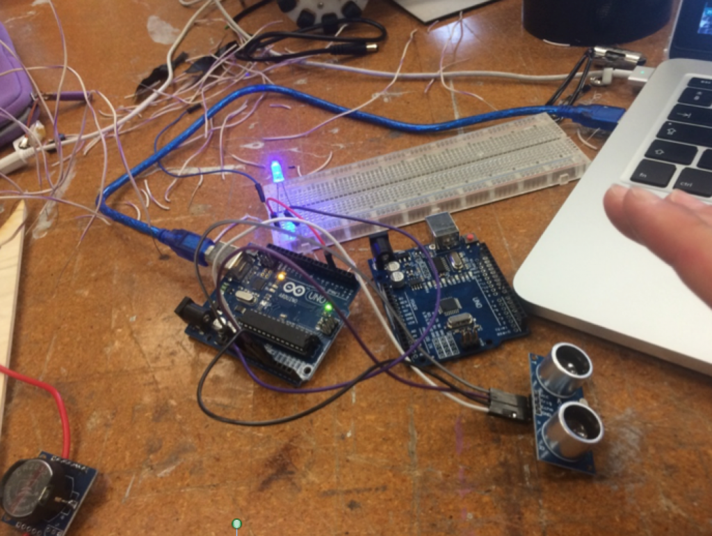
Since I couldn’t utilise 2 colours of LEDs, I’ve opted to include a proximity sensor to detect when the time is being checked. The design is now that it only becomes a clock when the sensor is triggered. For the rest of the time, its a light installation.

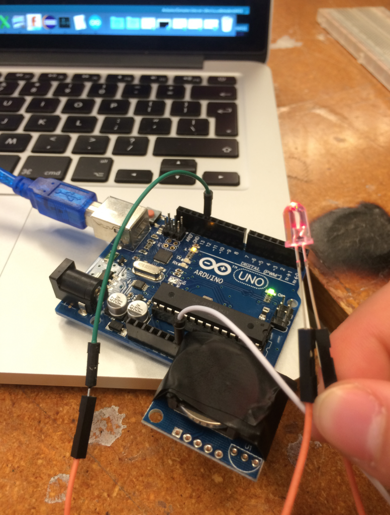
Heres the testing of the proximity sensor:

Note how the shadow cast by the pencil makes the hands of the clock and tells the time


(return to main navigation menu)

Progress through time

(return to main navigation menu)

Design, ideas, progress, challenges, and workarounds for my semester project. Part 2 of 5.

Part 1: Time for a semester project?

Part 2: Progress through time  (this post)

Part 3: Tick tock goes the clock

Part 4: What’s in a face?

Part 5: Closing Time


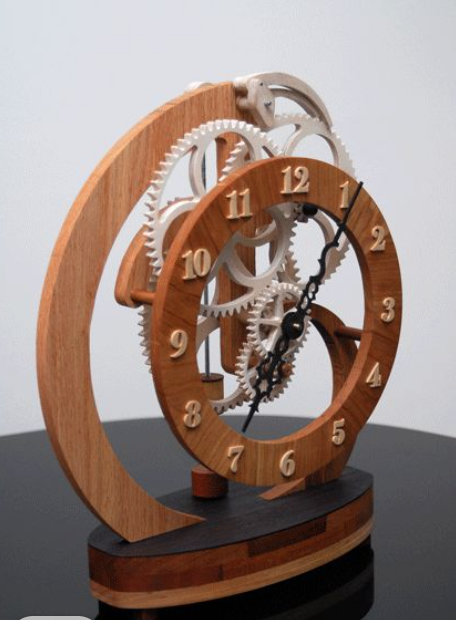
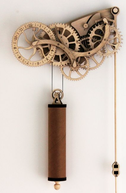
Realistically, there’s 2 routes I can take with creating a timepiece. Predominantly mechanical, or predominantly electrical. Cogs and wheels or LEDs and circuits?

Screen Shot 2016-05-02 at 15.33.04Screen Shot 2016-05-02 at 15.30.37Screen Shot 2016-05-02 at 01.25.21

Screen Shot 2016-05-02 at 01.23.16 Screen Shot 2016-05-02 at 01.23.40

Progress milestones and challenges:

early design and prototyping days

  • I started off by brainstormed ideas for a clock design that would utilise many making techniques.

Fixed design

  • With my love of the outdoors, the way the world works at the most naturalistic level, the fundamental equations and the beauty that can be seen through them, I feel that merging old time-telling techniques with modern techniques is a particularly fitting final project for me.
  • In the brainstorming process, Vishal suggested some form of interactive nature for the clock. I originally thought about proximity sensors to activate a screen displaying data or something (as an additional feature besides time-telling). The idea that I’m running with is that I want to keep a simple elegance about the design, in keeping with the simplicity of the concept. No need to clutter it with unnecessary features for the sake of making it sing and dance.

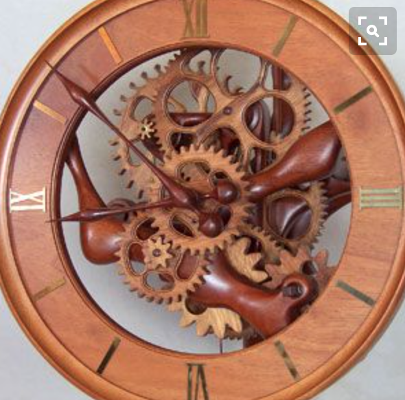
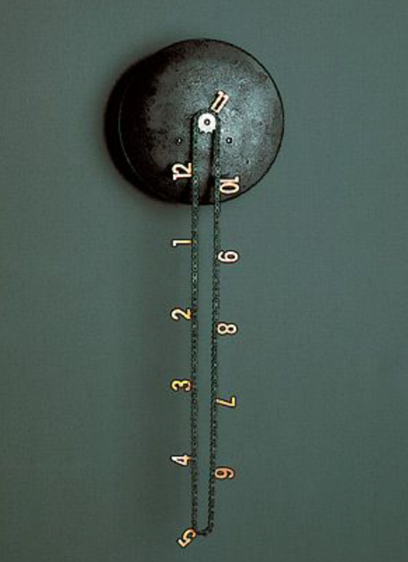
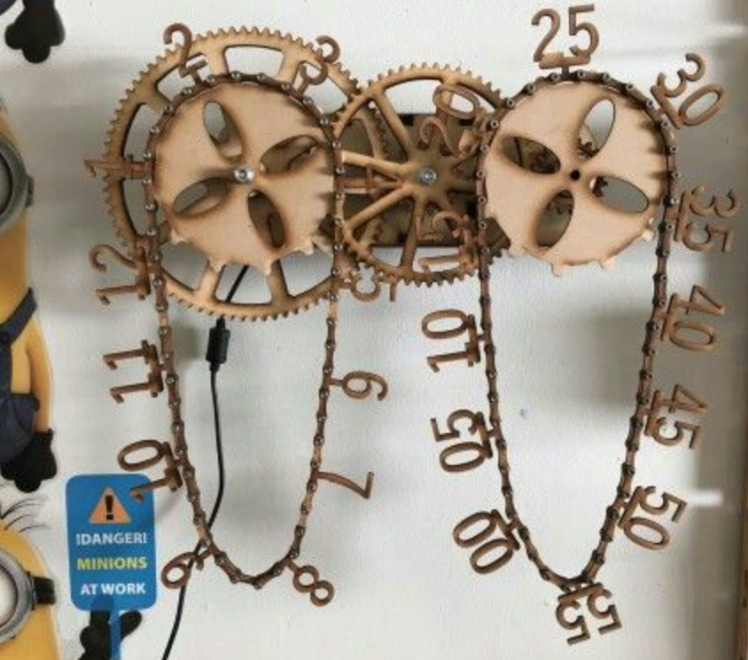
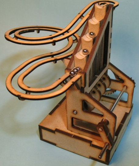
Looking at various mechanical designs as inspiration:

Screen Shot 2016-05-02 at 15.29.22 Screen Shot 2016-05-02 at 15.29.32 Screen Shot 2016-05-02 at 15.29.52

.

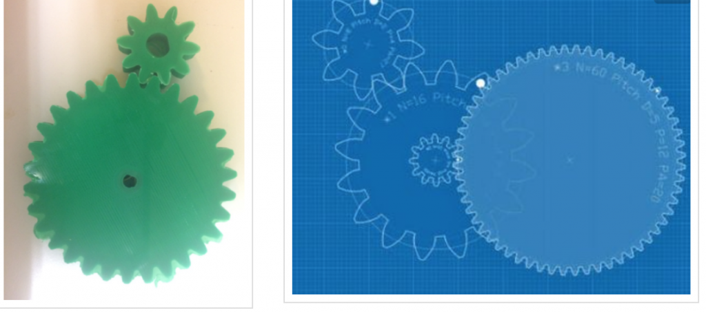
  • At first I printed some gears to see how feasible it would be to produce a mechanical-based clock.
Screen Shot 2016-05-13 at 16.36.34

Playing around with gear design and 3D printing gears

I found that the gears did not mesh well, and that it would be difficult to get smooth motion out of this.

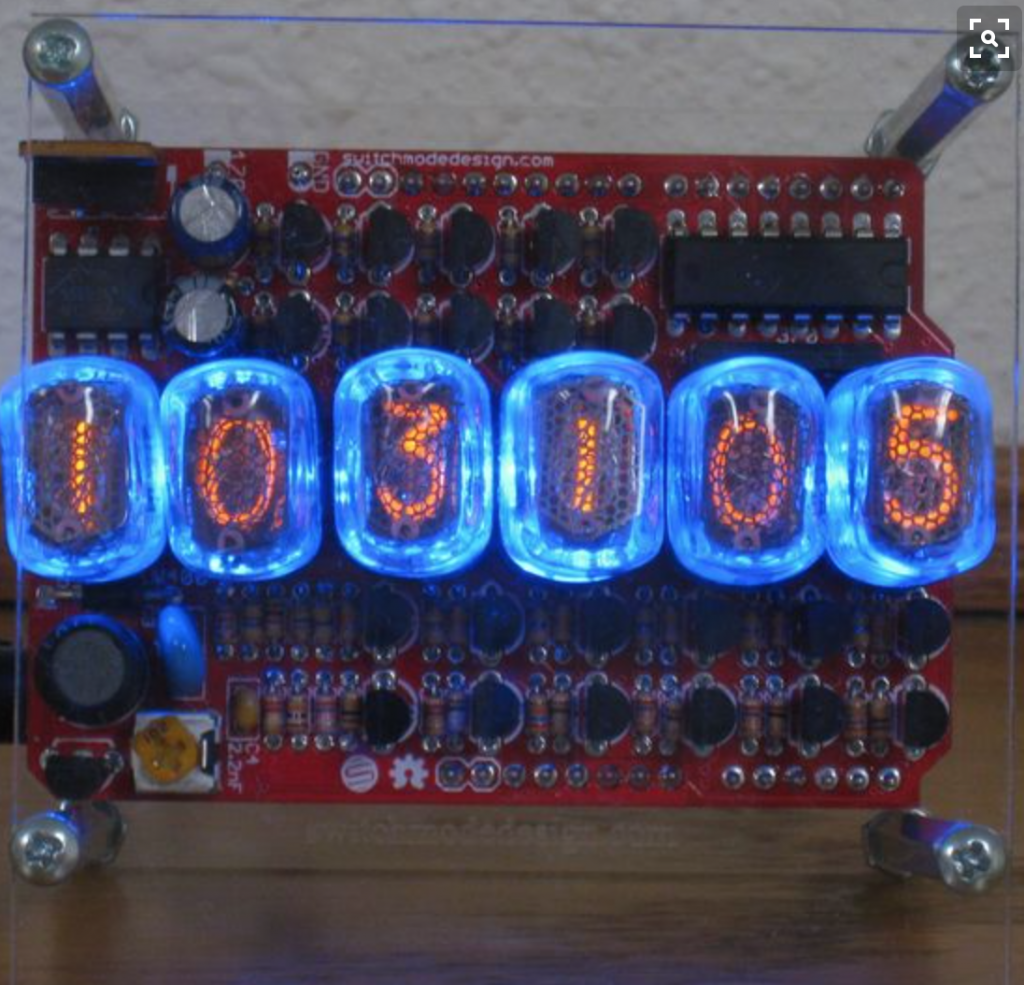
I then considered possibilities with LEDs and circuits:

Screen Shot 2016-05-02 at 15.32.08 Screen Shot 2016-05-02 at 15.32.14 Screen Shot 2016-05-02 at 15.32.29 Screen Shot 2016-05-02 at 15.32.38

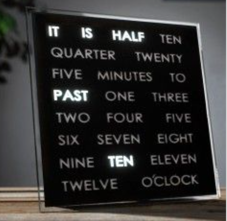
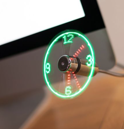
Different design approaches for LED clocks

.

Settling on an idea:

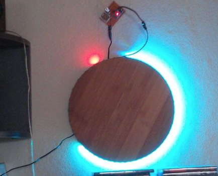
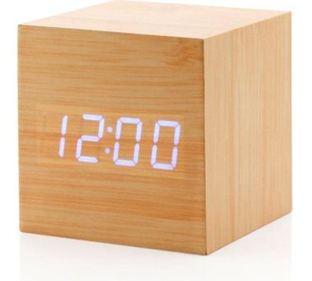
  • What I’m creating is a a clock face that relies on shadows to be the hands of the clock. Different LEDs in a ring will light based on the time, and shadows cast by those LEDs will show the time.
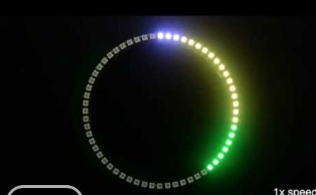
  • A similar concept was created as a design project in germany
Screen Shot 2016-05-13 at 10.33.49

concepts that i want to play around with

.

I got a time-keeping device working and talking with the arduino after some code bashing attempts. I’ve also managed to write some other code for the lighting of specific LEDs based on the time it reads from this device.

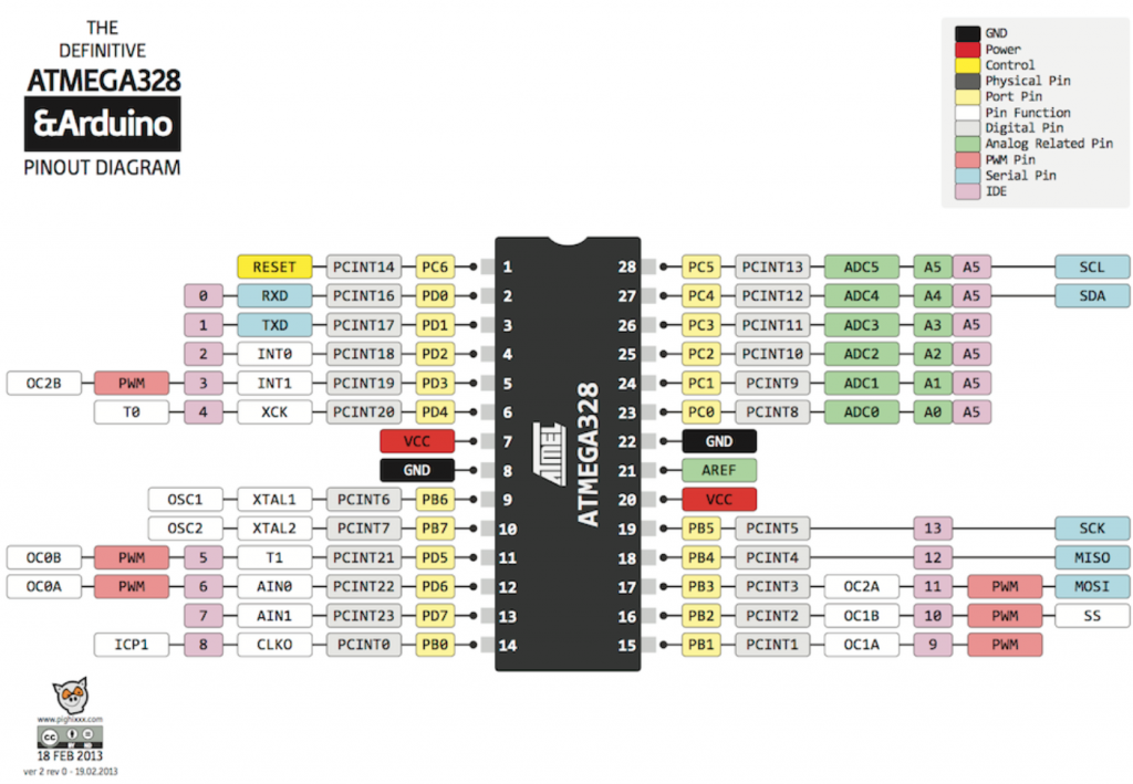
It utilises 2 rings of LEDs, with 2 separate colours. With a single arduino, its only possible to have 12 positions for LEDs. For more LEDs (ideal would be 60), a much more complex circuit would be required, with the use of charliplexing and many more man-hours of soldering and complexity.

Screen Shot 2016-05-02 at 01.21.39

From this diagram I can see that theres only 23 I/O pins, so my design is constrained to that

.

Working with the limitation of 12 IO pins on the arduino, I developed circuitry where each position has 2 LEDs in series wired like so:

Screen Shot 2016-05-13 at 09.44.12Screen Shot 2016-05-13 at 10.20.59 Screen Shot 2016-05-13 at 10.21.09

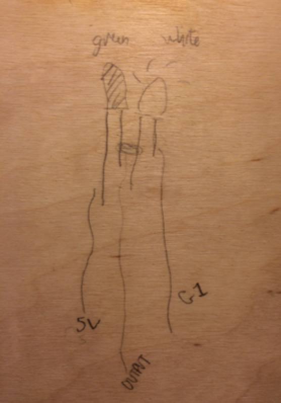
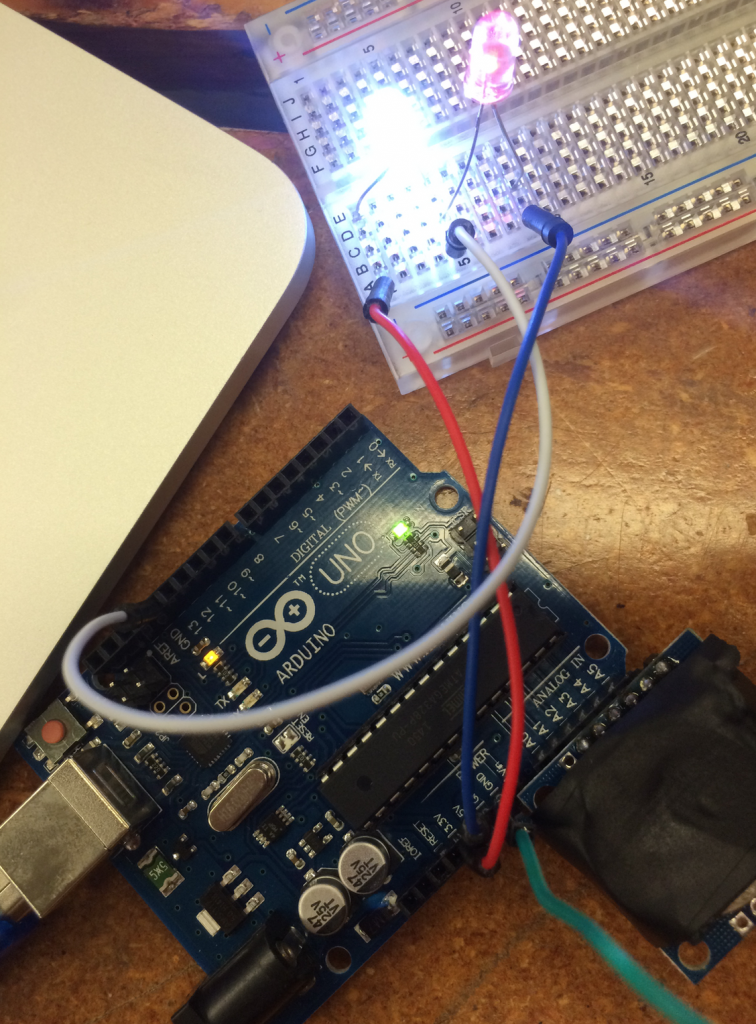
The concept works on a breadboard. While a low power is constantly running through, so the LEDs are low lit when not engaged, when the LED is chosen to light, it is significantly brighter than the others.

Screen Shot 2016-05-13 at 10.27.33

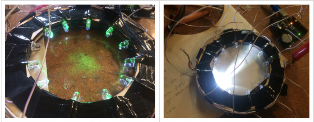
During the soldering process

.

Screen Shot 2016-05-13 at 09.44.40

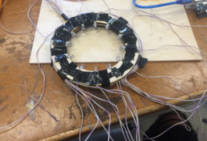
The parts are all soldered here, and wired up for testing. Unfortunately, with so many LEDs in the circuit, I found that the LEDs that should light brighter than the others do not have enough power to do so.

Screen Shot 2016-05-13 at 10.30.31

Testing the LEDs

Back to the drawing board.


(return to main navigation menu)

How To…. Engrave Glass

A post on my experiences and observations while rastering glass, and the methods I followed.

Refer to my first laser post (How to… laser cutting) about the general use and basics of laser cutting.
 .
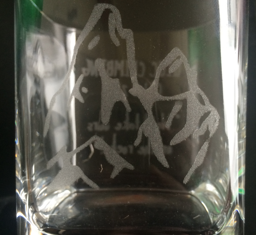
Screen Shot 2016-05-12 at 20.28.00 Screen Shot 2016-05-12 at 20.26.46
 .
Here, I’m looking specifically at rastering images onto glass. (The lasers that I’m using aren’t strong enough to vector cut through glass.)
To get a clear, well rastered image, settings have to be fine tuned, because the power speed, and laser movement vary per laser cutter. These settings also differ between the glass that you are restoring onto, since different glasses have a different composition and impurities.
 .
Screen Shot 2016-05-12 at 21.04.22
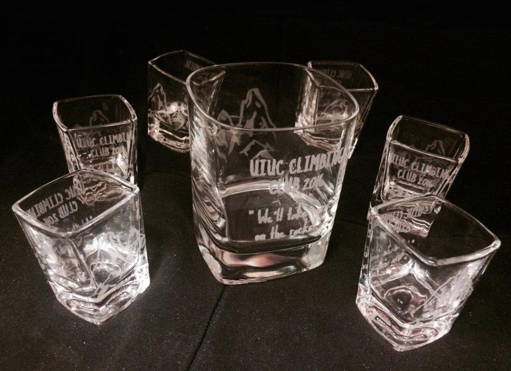
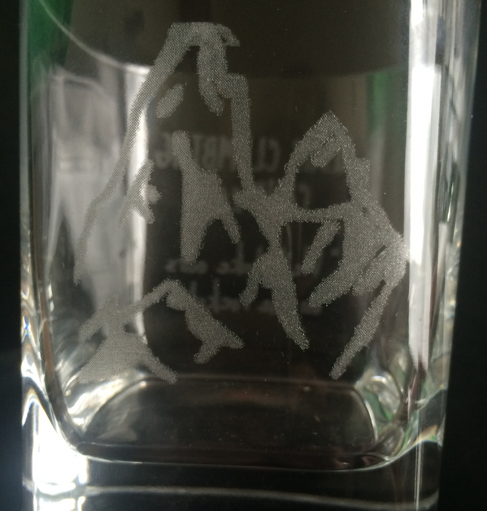
The final rastered pieces!

Procedural steps:
 .
Preparing an image for rastering (using Inkscape as an image editor)
  • Determine the size of the glass face that you will be putting the image on, and create a document of that exact size.
  • import your image in, and convert it to a vector file (black and white)
  • convert the image colour to 50% grey. This helps preserve the integrity of the glass and does not cut as deep. It also creates a “whiter” finish
  • (optional: tidy up the image)
  • place the image in the location wanted
  • export file as a PDF and save to a USB drive
Using the laser
  • turn on all fans and ventilation equipment
  • check laser is calibrated correctly and focus the laser, if not using the autofocus
  • open file on computer linked to laser cutter, and hit file, print
  • depending on laser cutter, settings are adjusted differently. in advance settings, select rastor, setting power to 100, and speed to a value between 20 and 40%
  • hit print on the computer, and on the laser machine.

Experimentation and learning:

Particular selections that I had to make were selecting rastor instead of vector cutting, setting the highest power possible (100), and testing various speeds and restoring styles to get the best finish.
I tried a series of test combinations:
black image, speed 50
black image, speed 40
50% grey, speed 40
50% grey, speed 30
For rastering my image, I found that a grey image at 25% speed worked best, and for rastoring text, black at 30% worked best on this glass. Also tried using grey text at 30 and 25%, but they both leave areas not quite fully rastered.
Another experimental point is the way the motion of the rastor cut: this was the difference between “standard” and “jarvis”.
 .
 Screen Shot 2016-05-13 at 09.28.56Screen Shot 2016-05-13 at 09.29.06
 standard vs jarvis
.
Rastering circumferential surfaces:
 .
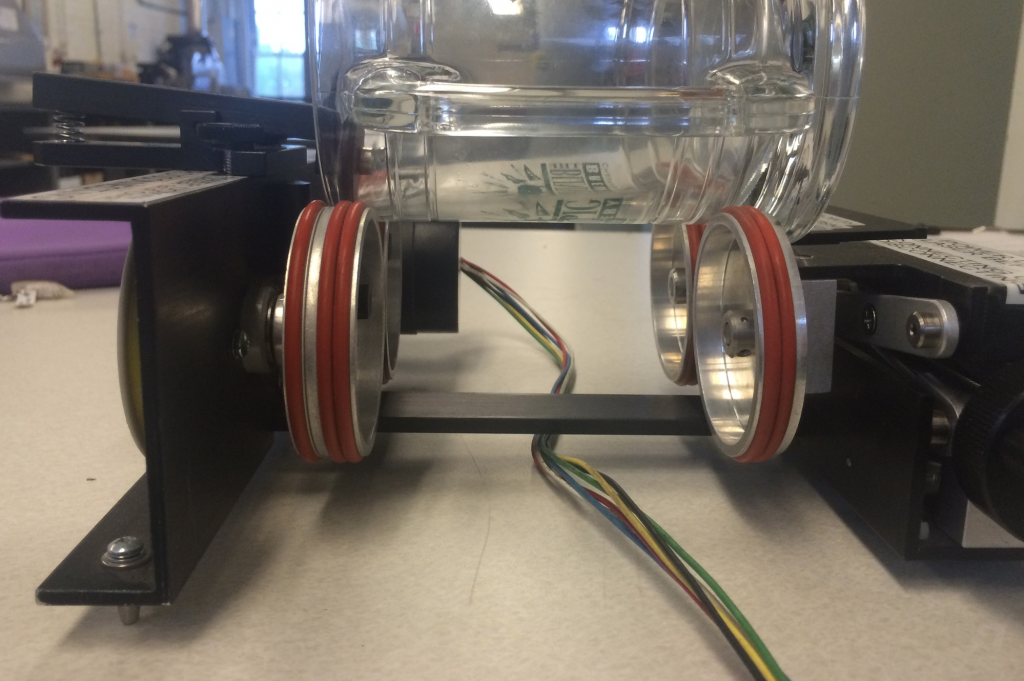
 The previous experimentation was all done on a flat surface so that the laser draws a flat image. To be able to raster onto a circumferential surface, a special jig must be used to rotate the surface as the image is engraved.
Depending in jig setup, a number of constraints must be considered for optimal engraving.
Screen Shot 2016-05-12 at 21.13.53
 .
 .
Non-varying diameter with no external protrusions is the best shape to use
for a circular glass.
Screen Shot 2016-05-12 at 21.02.25Screen Shot 2016-05-12 at 21.01.56
examples of suitable glasses 
 .
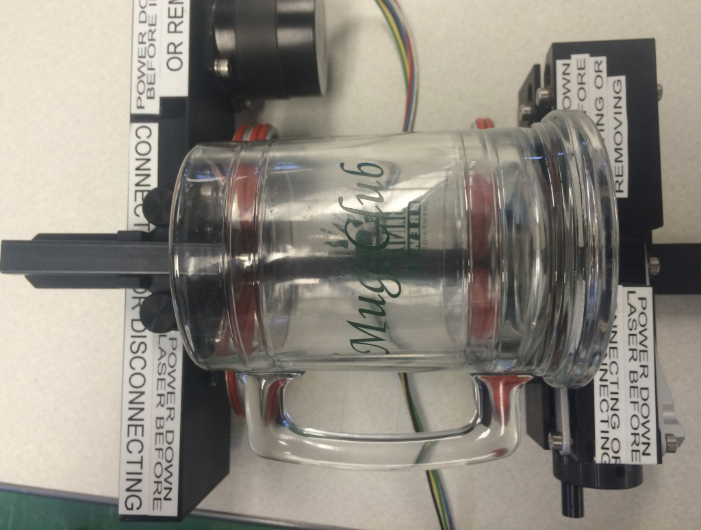
 Here is an example of a very inappropriate glass, which would not be possible to rastor onto easily:
Screen Shot 2016-05-13 at 09.26.42
 .
Features that make this inappropriate are:
  • handle will get in the way of the laser when the glass rotates, so a workaround would need to be considered in terms of the engraving space.
  • the base rim means that the glass does not sit level, which it needs to do for uniform rotation.
  • engraving area has to be planned very carefully. if it were a blank glass then it wouldn’t matter, but if I want what I’m engraving to line up with what is already on the glass, then careful measurements have to be made.


(return to main navigation menu)


Tuna-lele Final Project

Inspiration:
A little less than halfway through the semester, Josh Matthew and Johnny were sitting in the Champaign-Urbana Community Fab Lab trying to figure out what our semester project was going to be. We were learning how to laser cut notebooks and etch designs into them when Annie Guo overheard them and told them she also needed a project team. They were more than happy to invite her to work, but no ideas were coming to their minds.

They decided to start a Facebook group message that night to try and decide on a specific project. Later that night, Johnny came across a video for a Kickstarter project for “Roadie” a Bluetooth motorized guitar tuner. Johnny messaged Annie and Josh immediately about maybe doing a similar design for an acoustic ukulele tuner and they all discovered that each of them knew how to play the ukulele! They had found our idea and were ready to get started. They all played the ukulele and they thought it would be a great idea to build an automatic tuner, combining the different skills they learned from the fab lab.

Inspiration video: https://www.roadietuner.com/
Research:
They knew this tuner was a bit of an ambitious project, but they pursued it (even though none of them were CS majors or understood any ECE…) because it combined many of the aspects they learned in the Fab Lab. They knew their design would include an Arduino for the tuning portion and 3D printing for the piece that attaches to the peg. They were still a little bit curious about the code, so they figured research started with Google.

They were able to find a similar Instructable (http://www.instructables.com/id/Automatic-Guitar-Tuner/) but the problem was that electric guitar are able to be plugged right into the computer to measure the sound waves! They couldn’t do that with our acoustic ukulele, which means they needed an outside microphone to pick up the sound frequencies. They also learned that the frequency for each string of a ukulele is set. Pitch is correlated to a frequency, so Annie figured in the code she would be able to hardcode each set frequency.

G: 392.00 Hz
C: 261.63 Hz
E: 329.63 Hz
A: 440.00 Hz

They divvied up roles and decided Annie would be in charge of the coding of the Arduino, Josh would be in charge of design, Johnny would help out with design and PowerPoints/extra assignments. Each party started researching their respective roles and began researching different pieces of code and design.
Design:

When first considering designs, Josh and Johnny knew that they had to have an Arduino casing, and a part that would attach to the tuning peg of the ukulele so that it could turn it automatically. They were joking around and one of us came up with the idea of calling our project the “Tune-a-lele” which eventually turned into a fish pun and having the part look like the head of a fish.

As silly as it was, if they were ever going to market the product it would at least have an awesome name! After multiple tries in Autodesk Fusion 360, they finally settled upon the idea of using a file from Thingiverse and modifying it to their needs. They were able to create a rectangular clip at the end of head that would turn the peg, however when this ended up being too big, they finally created a small cube, with a printed fish sticker that would turn the peg without touching the others. Now that they had the design, it was time to code!
Software and Hardware:
When Annie first started considering the code and the hardware, the hardest part was figuring out all the connecting components. She knew she needed a component that would pick up the frequency of the string selected, a piece of code that would match the frequency of the string that is plucked versus the frequency of the perfect pitch, and a piece of code that would rotate the servo motor left or right depending on if the pitch was too high or too low.

For the code, she knew she needed to use a Fast Fourier Transformation, thanks to Colten. This is a classic technique used in Arduino audio signal processing, so she downloaded an FFT library from Arduino and incorporated it into the code. It converts the time series signal the microphone picks up into a representation in the frequency domain. She needed the frequency the mic picks up because the algorithm is supposed to match the frequency the mic picks up versus the hardcoded perfect frequency.
The first iteration of the hardware involved using a contact mic to simulate how an electric guitar picks up vibrations. A contact mic (also known as a piezo mic) is put on the body of the ukulele, and is connected to the Arduino. Unfortunately this did not pick up the signal as well as they wanted for the code.

The second iteration of the hardware involved just a regular electret spark microphone. This was connected to a breadboard which was connected to the computer and the code. This iteration worked, and was able to pick up the frequency they needed, but only in an incredibly quiet environment.

Lastly, they attached the 3D component to the servo motor that was programmed to rotate up or down according to the pitch. They made sure the motor had enough torque to actually move the peg—this motor does!
Test Run:
It worked! https://www.youtube.com/watch?v=PkXWCXKTg-I

Future Iterations:
They were able to learn a TON on audio signal processing (lots of information and math that was truly over our their heads) but, in the end, it was a chance to practice real world building. In most business classes, they never got the opportunity to watch an idea come to life, so that opportunity was truly an incredible process. Another skill they learned as the ability to segment the components they needed in order to divde up the work. For this particular project, they needed something to pick up sound wave, a piece of code to process the sound wave, a piece of code to match the wave picked up versus what it should be, a piece of code to spin the motor higher or lower depending on the pitch, and a 3D component that will attached to the peg. Being able to divide up our project into these simple steps allows us to modulate the project so the group can all work on different parts.
For future iterations, Annie suggested testing the mic on the string. Maybe that would be an even better version than the contact mic they had built. If the mic was settled right on the string, it would probably pick up the vibrations of the single string
She also suggested a low pass and high pass filter to extract excess audio. Because this microphone picked up a lot of residual sound, it was really only possible to work if the room was dead silent. Obviously, there is a lot of ambient sound in the environment, and they would love for the tuna-lele to work regardless of the environment. A low pass and high pass filter would filter out the frequency that did not fall within the range, leaving a sweet spot for the code to only react to what the microphone would pick up between the suitable range. We would need different filters depending on the string we wanted to pick.


-Annie, Josh, Johnny 🙂

MakerLab Bot

Working with a Raspberry Pi for my end of semester project has been incredibly
challenging and yet a very educational experience.  One of my favorite parts of this class is that there is no rigid structure to follow for
a final project in the sense that I was able to do anything.  Although the idea for this project came for the MakerLab’s ‘need’ for a voice-recorder/prompting robot, the usage of a raspberry pi was very open ended.
The major drawback of working with a project that either works or doesn’t, and has
minimal build required apart from the body, is that until it works, one has little to show
for the several hours and days invested in research.  Simply setting up the pi from my laptop as opposed to hooked up to a monitor as is it’s default, took several trial and error attempts at various tutorials.
Harina used a lasercutter to get the body of our stationary robot to be functional as well as cute.  The whole selling point of making people want to interact with a robot sitting on a desk is that it’s cute and cool.  The back interlocks with the front so that all the wires aren’t sticking out once the Bot is fully functioning, as well as easily accessible for fixing bugs.
I ended up using ssh, a command that lets you commandeer the terminal of any other computer given their privacy settings allow, and you know the password!  Our presentation goes through all the intermittent steps that I found from this project.
Nevertheless, I was able to get some things to work.
I have managed to get audio to record, save, and play back on command! The commands I used were:
sudo modprobe snd_bcm2835
arecord -D plughw:1,0 test.wav
aplay test.wav
I am currently working on getting the audio files to either save on another computer, or to connect the start and end of the recording process to buttons.  I will continue to work on this part of the project in between studying for finals in the next few days, though I will probably leave the MakerLab Bot in the lab by Wednesday.


Smart Glove Wrap-Up and Documentation

Taking this Digital Making course this semester was possibly one of the greatest decisions I’ve made thus far. I first found out about the course through a previous student of Vishal’s and teammate of mine, Arielle Rausin. She was always talking about 3DP and printing gloves for the team – and I thought that was cool; I wanted to be a part of it.

The first day of class was a little overwhelming. I remember it clearly. Under the assumption that 3D Printing capabilities were limited to wheelchair racing gloves, my mind was blown when we were shown the different methods of printing and the endless possibilities of things to make. This is where my problem started: too many options!

We were then told that we would have this huge semester project where we needed to create something just because, or to solve a problem. My mind was drawing such a blank and I hadn’t the foggiest on what to do. As the semester crept on, so did my anxiety about this project, looming in the background.

When we were visiting the FabLab, messing around with Arduinos, I heard Vishal and Jeff talking about the possibilities of flexible filament, and a lightbulb went off in my head: apply that to the racing gloves.

Immediately I started throwing ideas around with Vishal and settled on a Smart Glove idea that could measure force, acceleration, and stroke frequency. Apparently, I was talking a little too loud, because I had a team at the end of that conversation: Pri, Toheeb, and Andrew.

As far as project scope went, Toheeb and I went to speak with Professor Rice in the Kines Department; he explained exactly what things we should be paying attention to and felt that this project was worth pursuing.

The next week, the three of them built a force sensor out of Arduino parts to see if the actual hardware was something feasible to be built.. and we had success!

The most difficult part of this project was actually coming up with the prototype to have proof of concept. Since the electronics were not very flexible, we had a little spot of trouble with getting everything to stick. All in all, I’d say that this semester was a success.

You can view our presentation slides here.

Project Overview and Documentation – Stirling Engine

Motivation 

Building a stirling engine has been a project that I have wanted to tackle for a long time now, but never had the resources. Through everything that we learned this semester, and the wonderful opportunities that were presented to us through Digital Making, I decided that now was my chance to finally fulfill this dream. Unlike many of the other projects, mine was focused on the question of whether I could actually complete a working engine, rather than its application in real world problems. However, an engine like this could be used to power any number of electronics like a desk light or a phone charger.

Ideation and Design

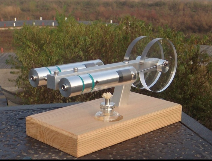
My research into this project began with understanding exactly how a stirling engine works, and the physical orientations that were possible when it came to designing the structure. There are multiple orientations for the layout of the pistons such as inline, side by side, offset, etc. I chose to do a side by side engine because it seemed like the most simple to design and offered the least amount of complicated pieces. Shown below is a nice looking stirling engine that has the same layout as the one I designed.

As you can see, the pistons are side by side, offering convenient support locations as well as easy flywheel design.

The main problem I encountered while designing the engine was trying to come up with a suitable material for the pistons. Since a flame would be used to heat the air, I couldn’t 3D print the pistons as they would melt under the heat. After much research, I noticed that a lot of home designs used these   borosilicate glass syringes as the work and displacer pistons. They are perfect for heat resistance and also offer the air-tight property that is needed for a stirling engine.
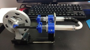
The build

Unfortunately, I did not take pictures of the pieces as they were being printed because I was just too excited to put them all together. IMG_20160502_243116473

This is the finished engine, in all its glory. Unfortunately, the glass tip of one of the syringes broke off when I accidentally dropped it, so some tape was needed to attach the silicon tube to the end of the piston. Also worthy of noting is the metal L-bracket that is attached to the engine. I neglected to account  for the strength of the support connecting the flywheel to the pistons, and the whole engine tends to flex as a result. The L-bracket prevents the bending from getting too severe.

Success (or lack thereof) and future work

To my disappointment, the engine does not work, the finished product should function something like this. I suspect that the issue is that I have made the displacement volume too much for how little inertia the flywheel provides. When the engine would be operating, a small low pressure environment should be created between the two pistons, however the force that this creates on the flywheel is too much to allow it to smoothly run between cycles. To correct this, I need to shorten the distance that the crank arms are away from the center axle, and possible make the flywheel heavier. Some other modifications I will make is thickening the base to prevent flexing, and sink the screws in the base to make it a flat surface.