Tuna-lele Final Project

Inspiration:
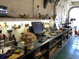
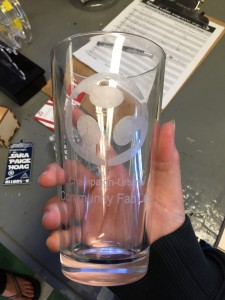
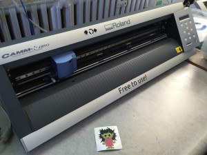
A little less than halfway through the semester, Josh Matthew and Johnny were sitting in the Champaign-Urbana Community Fab Lab trying to figure out what our semester project was going to be. We were learning how to laser cut notebooks and etch designs into them when Annie Guo overheard them and told them she also needed a project team. They were more than happy to invite her to work, but no ideas were coming to their minds.

They decided to start a Facebook group message that night to try and decide on a specific project. Later that night, Johnny came across a video for a Kickstarter project for “Roadie” a Bluetooth motorized guitar tuner. Johnny messaged Annie and Josh immediately about maybe doing a similar design for an acoustic ukulele tuner and they all discovered that each of them knew how to play the ukulele! They had found our idea and were ready to get started. They all played the ukulele and they thought it would be a great idea to build an automatic tuner, combining the different skills they learned from the fab lab.

Inspiration video: https://www.roadietuner.com/
Research:
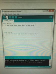
They knew this tuner was a bit of an ambitious project, but they pursued it (even though none of them were CS majors or understood any ECE…) because it combined many of the aspects they learned in the Fab Lab. They knew their design would include an Arduino for the tuning portion and 3D printing for the piece that attaches to the peg. They were still a little bit curious about the code, so they figured research started with Google.

They were able to find a similar Instructable (http://www.instructables.com/id/Automatic-Guitar-Tuner/) but the problem was that electric guitar are able to be plugged right into the computer to measure the sound waves! They couldn’t do that with our acoustic ukulele, which means they needed an outside microphone to pick up the sound frequencies. They also learned that the frequency for each string of a ukulele is set. Pitch is correlated to a frequency, so Annie figured in the code she would be able to hardcode each set frequency.

G: 392.00 Hz
C: 261.63 Hz
E: 329.63 Hz
A: 440.00 Hz

They divvied up roles and decided Annie would be in charge of the coding of the Arduino, Josh would be in charge of design, Johnny would help out with design and PowerPoints/extra assignments. Each party started researching their respective roles and began researching different pieces of code and design.
Design:

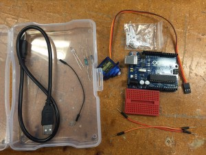
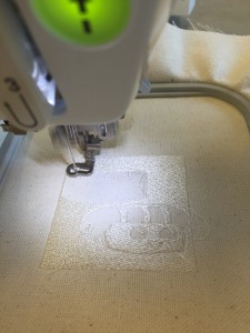
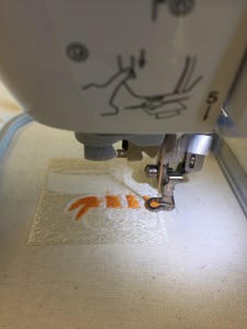
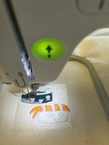
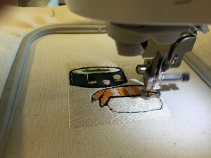
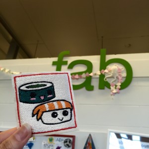
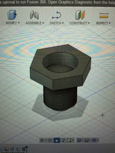
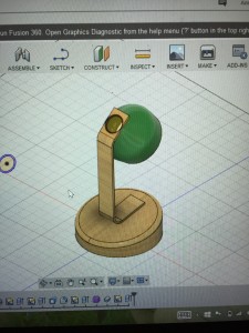
When first considering designs, Josh and Johnny knew that they had to have an Arduino casing, and a part that would attach to the tuning peg of the ukulele so that it could turn it automatically. They were joking around and one of us came up with the idea of calling our project the “Tune-a-lele” which eventually turned into a fish pun and having the part look like the head of a fish.

As silly as it was, if they were ever going to market the product it would at least have an awesome name! After multiple tries in Autodesk Fusion 360, they finally settled upon the idea of using a file from Thingiverse and modifying it to their needs. They were able to create a rectangular clip at the end of head that would turn the peg, however when this ended up being too big, they finally created a small cube, with a printed fish sticker that would turn the peg without touching the others. Now that they had the design, it was time to code!
Software and Hardware:
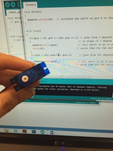
When Annie first started considering the code and the hardware, the hardest part was figuring out all the connecting components. She knew she needed a component that would pick up the frequency of the string selected, a piece of code that would match the frequency of the string that is plucked versus the frequency of the perfect pitch, and a piece of code that would rotate the servo motor left or right depending on if the pitch was too high or too low.

For the code, she knew she needed to use a Fast Fourier Transformation, thanks to Colten. This is a classic technique used in Arduino audio signal processing, so she downloaded an FFT library from Arduino and incorporated it into the code. It converts the time series signal the microphone picks up into a representation in the frequency domain. She needed the frequency the mic picks up because the algorithm is supposed to match the frequency the mic picks up versus the hardcoded perfect frequency.
The first iteration of the hardware involved using a contact mic to simulate how an electric guitar picks up vibrations. A contact mic (also known as a piezo mic) is put on the body of the ukulele, and is connected to the Arduino. Unfortunately this did not pick up the signal as well as they wanted for the code.

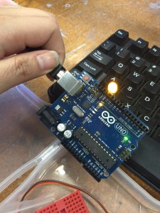
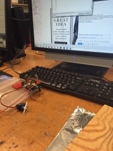
The second iteration of the hardware involved just a regular electret spark microphone. This was connected to a breadboard which was connected to the computer and the code. This iteration worked, and was able to pick up the frequency they needed, but only in an incredibly quiet environment.

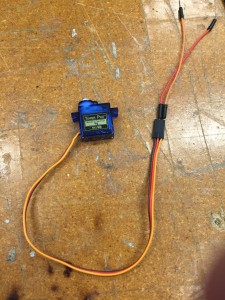
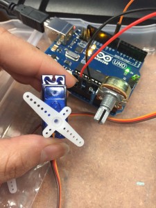
Lastly, they attached the 3D component to the servo motor that was programmed to rotate up or down according to the pitch. They made sure the motor had enough torque to actually move the peg—this motor does!
Test Run:
It worked! https://www.youtube.com/watch?v=PkXWCXKTg-I

Future Iterations:
They were able to learn a TON on audio signal processing (lots of information and math that was truly over our their heads) but, in the end, it was a chance to practice real world building. In most business classes, they never got the opportunity to watch an idea come to life, so that opportunity was truly an incredible process. Another skill they learned as the ability to segment the components they needed in order to divde up the work. For this particular project, they needed something to pick up sound wave, a piece of code to process the sound wave, a piece of code to match the wave picked up versus what it should be, a piece of code to spin the motor higher or lower depending on the pitch, and a 3D component that will attached to the peg. Being able to divide up our project into these simple steps allows us to modulate the project so the group can all work on different parts.
For future iterations, Annie suggested testing the mic on the string. Maybe that would be an even better version than the contact mic they had built. If the mic was settled right on the string, it would probably pick up the vibrations of the single string
She also suggested a low pass and high pass filter to extract excess audio. Because this microphone picked up a lot of residual sound, it was really only possible to work if the room was dead silent. Obviously, there is a lot of ambient sound in the environment, and they would love for the tuna-lele to work regardless of the environment. A low pass and high pass filter would filter out the frequency that did not fall within the range, leaving a sweet spot for the code to only react to what the microphone would pick up between the suitable range. We would need different filters depending on the string we wanted to pick.


-Annie, Josh, Johnny 🙂

Week 11– Scanning Technologies

This week for class we worked on 3D scanning and printing using two types of scanning technologies. One was on the ipad and used the camera and a piece of add on hardware and software to scan. The other was through propriety scanning hardware and software called geomagic.

The way the 3D scanning software works is it uses laser triangulation. Geomagic uses short-midrange laser triangulation and how it does that is the laser configuration scans across object, the sensor then picks up on reflections from all different angles, and it uses trig to finish up filling in any empty spaces.

I tried both the technologies and found that my hair (and the back of the chair) was where the real issues were when it came to using Geomagic. The ipad was able to scan the human head much better if you had a long sheet of flat hair. Both my partner and I could not get scanned using Geomagic but the IPad worked. When Harina put her hair in a braid, Geomagic worked. It is a much trickier technology to handle than I previously thought. The scans turn out pretty accurate though. I am interested in seeing how accurate scanning of a person versus an object is. I noticed there were two features through Geomagic so I would love to explore how scanning these two subjects affect the accuracy of the final STL file.


IMG_6788 IMG_6789

What we used to process the scans was Autodesk meshmixer—this is the software that is able to process the STL file that Geomagic saves it as. It was a surprisingly accurate scan. The only thing I wished I could see more nuances with were my eyes. I would say the capture was fairly accurate to how I looked that day. It was able to capture ruffles in my hair and specific details in my clothing so I was pretty impressed with the Ipad scan. Looking at my partner’s scan, I noticed it captured the details of her braid which was pretty impressive. It lost her glasses though. I would love to see how scanning technology improves as software gets more and more accurate.

Ariel also came in to talk about some more practical applications of 3D scanning besides just printing a scan of our bust. She used the scanning technology to get an accurate scan of the grip she uses for Paralympic wheelchair events. I could see scanning being very useful in the medical industry for customization of products. It would be a much faster fix if every hospital had a 3D printer to make custom casts or crutches.

Week 10– Back to the FabLab

Week 10:

This week for class we worked on Arduinos! Arduinos are “an open-source computer hardware and software company, project and user community that designs and manufactures microcontroller-based kits for building digital devices and interactive objects that can sense and control the physical world.” In other words, the Arduino boards we used in class are tiny microcontrollers that can be programmed to do things like turn a motor 360 degrees or turn an LED on and off.

This is what all the components look like:

IMG_6691

IMG_6696IMG_6692

You connect the arduino board to the computer and you use wires to connect Input output pins. There are 5 volt power to the reactor. You can turn the pin on and off.
Arduino is the name of the tiny computer and also the language that we will be writing in

The first thing we programmed was to turn LED on and off. The certain pattern comes from turning signal on and off in a certain manner.

IMG_6698IMG_6700

Second piece that we programmed was the Servo motor. Servos are controlled motors. You connect the servo motor with the three long cables. Power is red, ground is brown, and signal is orange. That means the red cable is connected to the 5V, ground is connected to 0V of power and signal is where you write the program and how the servo motor receives the signal. We were able to program the motor to spin in 360 degrees and then again between the degrees of 20-120 degrees. The practical application would be programming a children’s toy to be able to spin in a limited number of degrees so the children’s doll doesn’t look like the exorcist.

IMG_6697IMG_6699

Other applications of the simple CPU is a smart cutting board. We will be using the Arduino (or the more advanced Galileo) for our tuning piece.


Tuna-lele: Josh, Johnny and Annie’s Semester Project

Johnny, Josh, and I are working to build a device that recognizes different musical notes on a ukulele for our semester project. In essence, the device acts as a tuner. After last week’s Build-A-Printer event, we all discussed a few ideas as to how we should approach this project. Ultimately, we decided to break up the work by what each of us are most passionate about. Annie and I are extremely fascinated by the software aspect of what our project entails whereas Johnny is heavily interested in the design and aesthetic appeal of our device. To be quite honest, Annie and I didn’t really know what kind of software goes into a tuning device. After doing quite a bit of research, we both realized that we can incorporate an Arduino or a Galileo into our project and have it act as the foundation of the tuner! We have been experimenting with different microphones to pick up different soundwaves, which we think will be a great way for a tuner to pick up the pitch. As for the design, Johnny plans on creating a casing for the arduino so that it would not be damaged or easily tampered with through Autodesk Fusion and then 3D printed. We discussed a few ideas and thought of a funny pun we could use, and we finally decided to shape the casing into a fish and call our final project the “TUNA-lele.” Since all of us are inspired by music, this project has been very fun to talk about! However, as we’ve begun designing, we’ve encountered a few issues. The main difficulty will be the size of the Arduino in the casing, but we may be able to fix this once we design our first prototype. We are also playing around with the idea of making it Bluetooth enabled as a unique aspect of this project. We’re really excited to work on this and cannot wait to present our make at the end of the semester! We will be looking for additional help from the Gurus at the Fab Lab and will be working on our project at the MakerLab and the Fab Lab.

Week 8: Trippy RGB Waves!

This week, we worked with Trippy RGB Waves and Soldering!

In our continuous attempt to learn how to make things we’ve now added soldering as a technique we can apply to our final project!

Background: Soldering is a technique “in which two or more items (usually metal) are joined together by melting and putting a filler metal (solder) into the joint, the filler metal having a lower melting point than the adjoining metal.” What this means is, we can now employ the techcnique of connecting various electronic pieces together to make a whole, functioning component!

The solder we used is a 60% tin and 40% lead alloy that melts at 180 degrees. The soldering iron can get as hot as 350 degrees celsius!

This week, we made something called Trippy RBG Waves. It is a one color pixel, that changes color when it detects movement of the hand. If you wave your hand in front of the sensor, it detects your hand flips through Red-Green-Blue. If you don’t wave your hand in front of the sensor, the light flips through the spectrum of color going red to orange to yellow to green to blue to violet to magenta, and back to red.

IMG_6310IMG_6312

Thru soldering, I was able to turn this bag of electronic components…
IMG_6326

…into this! Follow along below.


Trippy RBG (Explained) in 10 Steps! 

1. Resisters (r1, r2, r3)
2. Infrared detector
3. Microprocessors
4. Capacitor (black and yellow one)
5. Led (2 and 1)
6. Switch
7. Programming piece
8. Click in top part of microprocessor
9. Battery case
10. Click in battery

We were lucky enough to have Mitch Altman (https://twitter.com/maltman23) come in to speak about how to Solder! This is a man who is the inventor of TV B-Gone (something I don’t personally support, haha) and co-founder of Noisebridge, one of the original hackerspaces in San Francisco. He is our resident soldering god, if you will, and he spent this class period highlighting the steps to make his trippy RBG! (More specific instructions here: https://www.tvbgone.com/cfe_trippyRGB_instructions.php)

IMG_6313

IMG_6317

Here is a picture of the soldering iron we used. You hold it with your dominant hand and grab it by the black part (the entire metal area of it hot to the touch and gets to be 350 degrees celsius so you will burn yourself). Unfortunately, I got a little too excited and accidentally burned off a chunk of my hair when I first used it, so that happened.

The solder is the spool of malleable silver wire. I was pretty surprised at how easy it was to twist around. I didn’t have any expectations because I really had no idea what soldering was, but I didn’t expect the metal to be so easily bendable.
IMG_6318

Each connection should be clean, which is why the tip of the soldering iron always needs to be cleaned off with the sponge between each new connection. You drag the tip of the soldering iron towards you on a small damp sponge and the metal immediately flecks off.

When you make the connection, the smoke that is released is pine sap vaporizing. The chemical inside the solder is called flux and it keeps the metal from oxidizing and also keeps the metal clean.

IMG_6314

The first components we connected were the resistors to the PCB (printed circuit board). The wires sticking out of the resistors are called leads.

IMG_6315IMG_6316

The leads go inside the little holes in the PCB the resistor lays flat on the front of the PCB.

IMG_6319

The wire leads are then bent at a 45 degree angle– Mitch’s preferred angle to use when creating connections. This is when you actually begin to make the connection. You place the tip of the soldering iron across the hole (held with your dominant hand) and make sure it is touching the metal lead as well. Then you hold the solder (with your other hand) and gently touch underneath the metal tip, but also touch the small hole.

This creates a connection like the one made out of the left wire lead. The right wire lead has not been connected yet. The melted solder is what connects the resistor to the PCB.

I was genuinely surprised by how fast a connection could be made. It didn’t even take half a second for a connection to be made so you had to be pretty precise with where you touched the metal tip. The first time, I kept touching the top of the metal tip of the soldering iron instead of underneath it, so I was wasting solder because it kept melting on the wrong side.

IMG_6320

As I continue along the steps, here is another photo documenting my progress– I’ve finished all the resistors and added the infrared detector. This is what detects your hand if you wave it in front of the Trippy RGB Waves Kit.

IMG_6321

Here I’ve attached the microcontroller and a capacitor as well. As you can see, the letters sometimes, sort of, correspond to what component it is. C2 being the capacitor. R1, R2, R3 being resistors. I believe IC stands for integrated circuit. Each piece is soldered on, in the back. Since this capacitor is polar, it is important to remember to put this circuit in with the positive side as the longer lead.

One thing to note for attaching the microprocessor is that I had to hold the entire piece in place and bend the solder so it was standing up and tap it while holding the soldering iron and PCB. This was quite hard to do, and I almost burned myself, which I later found out is pretty common because most people don’t know how to hold the components.

Tip: Do not touch the board anywhere the soldering iron touches. At 350 degrees celsius, the board gets pretty freaking hot. If you hold the board by any part that gets touched by the iron, even on the other side, you will burn yourself.

IMG_6324

Another capacitor is connected (but this one is not polar, so the length of  the leads does not matter). The RGB LED, IR emitter, and on-off switch is also connected. This thing is just missing the battery holder and battery!

IMG_6323

This is what it looks like from the back. I also attached the battery holder and clicked in the battery, but failed to get a picture of that.

IMG_6330

…And there you have it, folks! You flick that switch on, and boom! Trippy RGB Waves Kit is complete! Thanks, Mitch Altman!


So what have I learned? I’ve learned a lot about how to solder, tips and techniques to not get burned, but beyond that, I’ve learned that a business student really has what it takes to pick up skills that I thought were only taught in engineering courses. I have been able to expand my knowledge even further about how to turn an idea into a tangible product, and I really think there are a lot of possible applications. I wonder how large scale manufacturing uses soldering in projects. I did a little more research outside of class, but it appears plumbers also do a lot of soldering as well!

Going forward, I really want to do more with soldering. I’m hoping this is something I can incorporate into my final semester project, but because it seems like the capabilities are endless!

Lasers Lasers Lasers!

Image

As you can probably tell from this week’s title, this blog post will be about the laser cutters in the Fab Lab! The Fab Lab has 2 Laser cutters that allow you to print and design many different objects from many different materials. But before I get into what I made and what I did, let me preface by explaining what I learned before the actual printing.

Laser Engraver Lesson:
We began by learning how to convert an image into something that could be interpreted by the laser cutters. The lesson was focused on Inkscape. Inkscape was the software we used to design the image we wanted to engrave. Our TA recommended selecting an image that was a silhouette because lasers cannot tell the difference of various colors and it was easier to pull out a bitmap from a vector image from a silhouette.

We learned about the difference between rastering and vectors. Rastering is an image made from many blocks (ie. when you zoom up really, really close to an image and you see it is made from blocks of color). They are referred to as pixels. Vectors use math to draw lines, shapes, and curves. They help retain great picture quality through scalability.

For my laser image, I took a silhouette of a bamboo tree and traced the bitmap. Then I deleted the actual image and used the bitmap image for the correct cut. I added more quotes and changed the size of the image to fit a notebook.

I learned more about the different materials that could be used for lasers. One type of material is acrylics. Acrylics make for really great cuts. As you can see, on the left an example of vector cutting and on the right you can see an example of raster engraving. You use both techniques for one image. Vector cutting is good for cutting the outline. Rastering is good for the inside if you want to cut out

Other materials that also work great are leather, wood, and glass.

These laser printers can even anodize metal– most water bottles, metal ones, have a layer of anodized metal, which the laser cutter can raster through. The only material it cannot cut is PVC, because it would ruin the laser optics and kill us because of the material and fumes it would release. (Lovely).

Something I thought that was really interesting was how you could adjust the grey scale on the wood as well.

My Laser Project:

In this picture of above, you can see my bamboo silhouette beginning to be rastered out.

Here is how the final product looked like! Something I was really surprised about was how accurate the words actually printed. Compared to the digital embroidery, lines were really hard to print. For the laser cutters, lines and words were really easy to print out– I was left wondering what the laser printer had a hard time printing. When I asked Gwen, it seemed designs that were extremely intricate were hard to print out.

I had some extra time to do another project and I wanted to see the effects of laser printing on wood, so I vector cut this logo for MakerGirl! I, unfortunately, didn’t have time to raster this entire image. Another thing I learned is that cutting this image takes only 5 minutes for a 5×7 inch image. If I wanted to raster the insides of the image, it would take upwards of 30 minutes for a 5×7 image.

Takeaways:
Again, I’m incredibly excited about how to combine all these making techniques. As I am going about considering my semester project, I am trying to figure out how to combine arduinos with laser cutting and digital embroidery and 3D printing! I probably won’t be able to get everything, but I definitely want to make something that combines at least 2 of these 4 elements…

Semester Project: Thought Process
So far, Josh, Johnny, and I have thought about making a digital 3D printed bluetooth tuner for our ukeleles. All of us enjoy playing the Uke and we all have a mutual interest in music, so we started with this. We’re still working on fleshing out the final idea.

Champaign-Urbana Community Fab(ulous) Lab

Last week we had the opportunity to visit the Champaign-Urbana Community Fabrication Lab! My first thought as I entered the building was why was this resource was so far away from most of campus! It’s located right by the ACES library so it is a little bit away from where I would’ve thought most students would want to use.

When I entered the lab, I was immediately struck but how… start-up-y it looked. There were design elements all over the room. We started the class with an introduction to the mission of the fab lab. Apparently there are resources like this all over.

Mission:

The foundation of the lab is built on 4 core principles: art, education, research, and entrepreneurship. It is a “makerspace” workshop space with the resources and capabilities to complete rapid prototyping and computer-based design work. The employees and volunteers are open-source “Makers” (us!) that work to turn an idea to a real, tangible piece of product. The lab is open to the pubic and welcomes staff, volunteers, students, and people in the Champaign-Urbana area to learn and create. Its a multi-disciplinary workspace from inspiration to iteration.

Walkthrough of the Lab: 

As I was walking through the lab, my eyes lit up by everything I saw. I couldn’t believe a resource existed like this on campus and wasn’t advertised more. I’m so sad I saw this on my last semester on campus! I would have loved to explore this community more but I’ll make the most of my semester now.

IMG_6033 IMG_6034

IMG_6035

You walk in and you’re immediately greeted with the variety of tools and applications. You can literally make anything you want in this place! The world is your oyster 🙂

IMG_6036 IMG_6037

Next week, we get to play with the lasers! The lasers allow cutting of plastics and into pieces of glass like the photo on the right.

IMG_6038 IMG_6039

There is a room for electronics where we will spend a week learning about arduinos.

IMG_6040 IMG_6041

There is also a section of the room that I spent this week on. It was focused on digital embroidery. To the left is a project that an art student is working on. To the right is a photo of a bad that has solar panels placed in. The solar panels allow for a phone to be charged straight from the bag! Apparently, Kate Spade is also launching a bag similar to this model. How cool is this?! Could be great for campers.

IMG_6042 IMG_6043

These two photos are of a sticker machine inside the fabrication lab. The top photo is entirely made of stickers.


Digital Embroidery Lesson:

IMG_6045

For this week, we used open source software and edited an image to be embroidered. I choose an adorable sushi picture I found off the internet! What the open source software allows is for you to blend colors out so you aren’t left with too many different threads. Each color left in this image represents a color of thread. My sushi picture had 6.

IMG_6046

Then we saved the image on the flash drive and hooked up the sewing machine to a computer with the flash drive saved. These sewing machines automatically loaded the image and each color was printed as a layer. All I had to do was load the thread color I wanted. First color was white.

IMG_6047

Second layer was the body of the shrimp sushi! A orange thread was used.

IMG_6049

3rd layer was the pink cheeks and 4th layer was the avocado green filling inside the sushi roll. This 5th layer was the dark green seaweed body (this picture above).

IMG_6051

The final layer and color was the black outline around the entire sushi and the eyeballs. Interestingly enough, if the line is too thin, this sewing machine has a really hard time printing really exact lines. Text can be really hard for this machine to print, so the advisors said shy away from too thin of lines.

FullSizeRender (7)

The software also allows you the pick how the thread is layered (the texture and the fill amount). In the end, this is how my final produce looked like, and I was so happy!

Takeaways:

I always forget that this class is about so much more than 3D printing. It is about promoting the idea of “making” as a design process and emphasizing the use of rapid protoyping. I am truly astounded to see how technology can be used to design quick, efficient prototypes. I am amazed at the incredible resources we have on campus. I am delighted that the students get a chance to learn from these incredible “Makers” in this community. I just wish that more students could see this opportunity and create something they truly enjoy as well.

My Confusion with (AutoDesk) Fusion

This week, we were blessed to be able to have a real instructor for Autodesk Fusion 360, and boy did I need one. Let me just say, straight off the bat, how difficult it was to navigate without watching proper videos and having proper instruction! Our first assignment from last week was to try and modify an existing template design (I choose a utility knife) or design something completely new from scratch. The first thing I did was struggle to even make any additionals to the utility knife. I kept accidentally removing the body or slicing away a part of the inside of the knife that was necessary. Frustrated with even the simple task of changing the color or type of material, I gave up modifying the utility knife and combined a couple shapes to make a haphazard “screw” (if you could even call it that.) I knew I was desperate when I hit the one hour mark left before class and my utility knife looked exactly the same as it did when I downloaded the example… Attempt #1 at Autodesk Fusion 360. Lovely.

IMG_6024

My two major takeaways from this week:

1.) Designing takes (a lot more) time (than you think)! 

Such a simple takeaway, but one that is dramatically underestimated. Even in class when we had 3 hours to listen to instructions (well articulated, clear instructions) about how to navigate Fusion 360, I still had trouble keeping up with the pace! As Toheeb said, this class went from 0-100 in about 1 class period. I struggled to even keep up. I’m going to need a lot more outside practice to get up to the pace of designing as everyone else, but I look forward to the challenge. I also can’t underestimate how much time is needed for a project. If I want to make something by scratch, I have to understand that it takes hours and hours of outside class work, just to get an elementary sketch into the computer. And the complexity of all the different layers means you really need to be able to compartmentalize all the different parts that go into an object as simple as a pen.

In the end, I was super happy with my lamp and ran downstairs to show everyone in BIF, although I’m not sure they were as impressed with my handiwork as I was… It’s because they don’t know the sweat and toil that go behind creating something!

IMG_6023

2.) There are resources everywhere. (Youtube is the best). 

This one cannot be overstated. WATCH YOUTUBE! There are so many great resources to teach you so many different skills of Autodesk Fusion! Youtube literally saved my life last week when I had to desperately design something new. The screw took a little bit of time getting used to, but I hope to upload videos in the future for different design techniques instead of just watching them. There are a lot of gurus online though, and it is a great community to learn from if you are a visual learner like I am.

Ben-Tommy Eriksen was a great example that I watched. He really helped me in a pinch.

Overall, I can’t wait to see what ideas my classmates have for the rest of the semester. Fusion seems like a lot of work at first, but it’s a great way to visualize the feasibility of your design and tweak a model without paying for the material cost of design.


Week 3: Design for America

Design for America Process and Values
This week for class, we worked with people from Design for America (DFA) for a workshop. The DFA team is an RSO of interdisciplinary students that try to use design to solve problems. The foundation is to use customer-centric thinking to improve the lives of individuals—to solve real world problems to make lives easier.

Five DFA members began class by walking us through the values of DFA. They broke down the Innovation process into two segments: Development and Implementation. Design for America Process

The purpose of Development is to understand the problem. During development, you
1.) Identify— Get a better understanding of the challenges a consumer needs to face is the first step in solving a problem
2.) Immerse— Put yourself in the context of a consumer to understand the context of a problem and the real issues
3.) Reframe— Change the problem statement from an issue to an action item that you can act upon

The purpose of Implementation is to create the solution. During implementation, you
4.) Ideate— Brainstorm multiple solutions without judgment to get a large quantity of potential solutions
5.) Build— Develop the initial iteration of an object from a sketch to a working prototype
6.) Test— Check if customers find this item useful and iterate on improvements that can be made to the object

They also highlighted the most importance of other values during the design process such as making it tangible, being optimistic, documenting progress, asking for feedback, telling a story, iterating frequently, and reflecting regularly.

Solving a Problem
During the portion of the class that required us to exercise our design skills, we started with 4 character profiles with individual struggles. My team focused on Jessica—a blind girl whose handicap did not allow her to have a robust social life. Using this knowledge, we used sticky notes to come up with a ton of potential solutions—some great and some…well, mediocre at best. We reserved judgment until the end, as to not stifle any creativity. Using the idea we narrowed our problem down to the fact that Jessica was unable to attend tailgates. We thought about problems that Jessica might face if she did get to a tailgate and we determined that safety of her drink was a big issue. In the end we developed a potential object Jessica could use to keep her drink safe.

Eponymously named DrinkSafe, this is an object that is a finger-print activated, adjustable drink holder with a lid that only opens when the user activates it. This seems like a very simple solution because we thought about our problem statement why our problem statement existed.

IMG_5751

“Jessica has trouble socially with her peers on college” –> because she does not feel safe.

Using this knowledge, we developed DrinkSafe as an appropriate object to help Jessica feel safer on campus and in a social setting.

My Understanding
First of all, I loved this class. It focused on design-centric thinking and prototyping to solve a problem. I think a lot of times (and especially in this class), it can be easy to get distracted by how cool the technology 3D printing can be. I think it is important to realize that no matter how cool a piece of technology is, it won’t become commercialized until someone is willing to buy it. People won’t buy an item no matter how cool it is, unless it adds an aspect of value to their lives.

Something that solves a problem definitely adds an aspect of value.

This class helped me rethink about how I market a product. Instead of starting with the technology, I should be identifying a problem to help solve first. I should, then, see if the technology is able to solve this issue. In a way, this idea could be applied, not just to physical products, but also services and emerging businesses too.

This class also gave me a step-by-step framework to analyze and emulate innovation in every new product I create. I always thought of design and creativity as a spur-of-the-moment sort of iteration. I never thought about how creativity could be broken down into steps and harnessed into a more productive methodology. Now I see this is a process that can be repeated and reworked so I can get creative solutions in every problem I approach.

Implications
Going forward, I’ve learned to design with a user in mind. I’ve decided to keep a running list of problems to solve and potential solutions because I think this is how I can design a useful product. I’ve also learned to frame the problem I’m trying to solve using this template:

How can we __(verb)__ __(users)__ at/in/on __(place)__ to __(verb)__ __(noun)__.

This will help me summarize problems and narrow my mission for helping real people solve real problems.

Week 2 Reflections

Unfortunately this week for class, I was unable to attend because I had to attend a company visit through another one of my classes. Even though I did not get a chance to attend class, which looked really great, I was able to connect with my partner and finish the reading. From reading a couple different posts and talking to Nancy, I was able to determine the different websites used to create designs. I’m really jealous I didn’t get a chance to make an object last week! It seemed like a great opportunity to get used to the new Ultimakers, which I haven’t used before.

One post talked specifically about how 3D printing can be used to solve every day problems. For right now, I am still trying to wrap my head around the fact that 3D printing isn’t just a cool piece of technology. It is useful, too. I’m trying to think of common, everyday issues that can be solved through 3D printing. Personally, I thinking 3D printing is incredibly fascinating, but I am still trying to understand the different materials that can be used. In my mind, the current machines we own print plastic so most of my ideas have been revolved around plastic prototypes. In reality, 3D printing comes in many different sizes and shapes with a variety of material.

For my four objects, I chose a Springy Apple Cable Saver. I am someone who constantly breaks chargers (mostly my fault because I don’t store them very well.) I can see a plastic model as a great way to keep the cords from fraying and this is an everyday problem I face. I actually think this design if very practical and am not sure I would change much about it, but based on some user reviews, it seems that the actually specs do not lock in at the right places. I would look to change that to more specific measurements of my charger. http://www.thingiverse.com/thing:1091637

Another object I chose was a Towel Clip. I constantly toss my wet towel in the bedroom and I never hang it up, because I am lazy and didn’t install a clip on the first day of school before moving in. I could really see this piece as very practical. What I would change about it, is the fact that it still needs to be hung on a rod. I want one that is directly attachable to the wall. http://www.thingiverse.com/thing:3117

Another object I chose was a Crocodile Clip. This is similar to a chip clip, used to keep chips or other food fresh! This is another practical device that could be customized. It is functional and practical—the only thing I would chance is perhaps how long the crocodile is. It doesn’t make sense to me that the actually part that holds the chip bag together seems pretty thin. I would make the width of the crocodile bigger and shrink the length. http://www.thingiverse.com/thing:941177

The last object I chose was an Ergonomic Plastic Bag Handle. Another completely practical device, this is used to prevent plastic bags from cutting into your arms. I was thinking about designing something like this because I had to carry about 20 bags of groceries the other day when leaving from Walmart. Because I do not have a car on campus, I had to carry all 20 bags by myself and it was a large strain on my shoulders, arms, and hands. I am interested in how you take the design or your hand (from malleable clay) and transform it into a plastic hard print. This example is only for the right hand, but I would make and repeat for both hands. http://www.thingiverse.com/thing:3230

I definitely selected objects that were on the practical side, but I think practicality is important because that is something that will sell. Going forward, some questions I have are how to take more customizable features and scan them into hard prints.