This week, we worked with Trippy RGB Waves and Soldering!
In our continuous attempt to learn how to make things we’ve now added soldering as a technique we can apply to our final project!
Background: Soldering is a technique “in which two or more items (usually metal) are joined together by melting and putting a filler metal (solder) into the joint, the filler metal having a lower melting point than the adjoining metal.” What this means is, we can now employ the techcnique of connecting various electronic pieces together to make a whole, functioning component!
The solder we used is a 60% tin and 40% lead alloy that melts at 180 degrees. The soldering iron can get as hot as 350 degrees celsius!
This week, we made something called Trippy RBG Waves. It is a one color pixel, that changes color when it detects movement of the hand. If you wave your hand in front of the sensor, it detects your hand flips through Red-Green-Blue. If you don’t wave your hand in front of the sensor, the light flips through the spectrum of color going red to orange to yellow to green to blue to violet to magenta, and back to red.
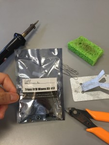
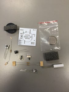
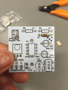
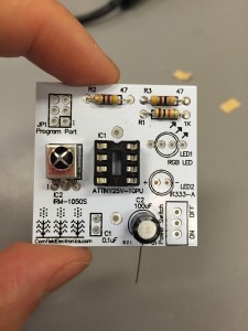
Thru soldering, I was able to turn this bag of electronic components…
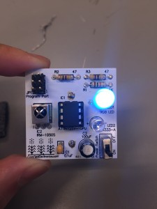
…into this! Follow along below.
Trippy RBG (Explained) in 10 Steps!
1. Resisters (r1, r2, r3)
2. Infrared detector
3. Microprocessors
4. Capacitor (black and yellow one)
5. Led (2 and 1)
6. Switch
7. Programming piece
8. Click in top part of microprocessor
9. Battery case
10. Click in battery
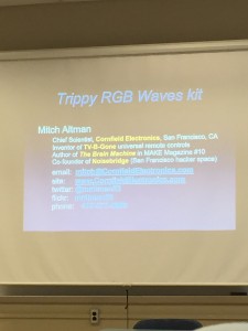
We were lucky enough to have Mitch Altman (https://twitter.com/maltman23) come in to speak about how to Solder! This is a man who is the inventor of TV B-Gone (something I don’t personally support, haha) and co-founder of Noisebridge, one of the original hackerspaces in San Francisco. He is our resident soldering god, if you will, and he spent this class period highlighting the steps to make his trippy RBG! (More specific instructions here: https://www.tvbgone.com/cfe_trippyRGB_instructions.php)
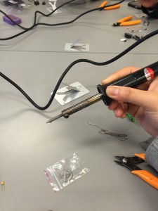
Here is a picture of the soldering iron we used. You hold it with your dominant hand and grab it by the black part (the entire metal area of it hot to the touch and gets to be 350 degrees celsius so you will burn yourself). Unfortunately, I got a little too excited and accidentally burned off a chunk of my hair when I first used it, so that happened.
The solder is the spool of malleable silver wire. I was pretty surprised at how easy it was to twist around. I didn’t have any expectations because I really had no idea what soldering was, but I didn’t expect the metal to be so easily bendable.
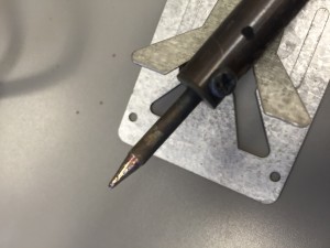
Each connection should be clean, which is why the tip of the soldering iron always needs to be cleaned off with the sponge between each new connection. You drag the tip of the soldering iron towards you on a small damp sponge and the metal immediately flecks off.
When you make the connection, the smoke that is released is pine sap vaporizing. The chemical inside the solder is called flux and it keeps the metal from oxidizing and also keeps the metal clean.
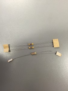
The first components we connected were the resistors to the PCB (printed circuit board). The wires sticking out of the resistors are called leads.
The leads go inside the little holes in the PCB the resistor lays flat on the front of the PCB.
The wire leads are then bent at a 45 degree angle– Mitch’s preferred angle to use when creating connections. This is when you actually begin to make the connection. You place the tip of the soldering iron across the hole (held with your dominant hand) and make sure it is touching the metal lead as well. Then you hold the solder (with your other hand) and gently touch underneath the metal tip, but also touch the small hole.
This creates a connection like the one made out of the left wire lead. The right wire lead has not been connected yet. The melted solder is what connects the resistor to the PCB.
I was genuinely surprised by how fast a connection could be made. It didn’t even take half a second for a connection to be made so you had to be pretty precise with where you touched the metal tip. The first time, I kept touching the top of the metal tip of the soldering iron instead of underneath it, so I was wasting solder because it kept melting on the wrong side.
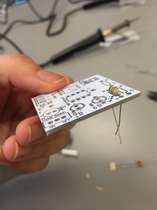
As I continue along the steps, here is another photo documenting my progress– I’ve finished all the resistors and added the infrared detector. This is what detects your hand if you wave it in front of the Trippy RGB Waves Kit.
Here I’ve attached the microcontroller and a capacitor as well. As you can see, the letters sometimes, sort of, correspond to what component it is. C2 being the capacitor. R1, R2, R3 being resistors. I believe IC stands for integrated circuit. Each piece is soldered on, in the back. Since this capacitor is polar, it is important to remember to put this circuit in with the positive side as the longer lead.
One thing to note for attaching the microprocessor is that I had to hold the entire piece in place and bend the solder so it was standing up and tap it while holding the soldering iron and PCB. This was quite hard to do, and I almost burned myself, which I later found out is pretty common because most people don’t know how to hold the components.
Tip: Do not touch the board anywhere the soldering iron touches. At 350 degrees celsius, the board gets pretty freaking hot. If you hold the board by any part that gets touched by the iron, even on the other side, you will burn yourself.
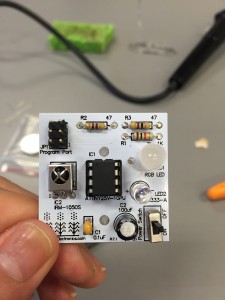
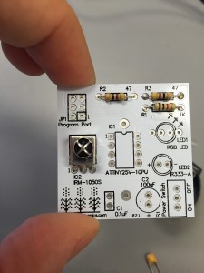
Another capacitor is connected (but this one is not polar, so the length of the leads does not matter). The RGB LED, IR emitter, and on-off switch is also connected. This thing is just missing the battery holder and battery!
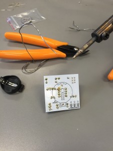
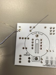
This is what it looks like from the back. I also attached the battery holder and clicked in the battery, but failed to get a picture of that.
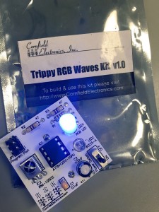
…And there you have it, folks! You flick that switch on, and boom! Trippy RGB Waves Kit is complete! Thanks, Mitch Altman!
So what have I learned? I’ve learned a lot about how to solder, tips and techniques to not get burned, but beyond that, I’ve learned that a business student really has what it takes to pick up skills that I thought were only taught in engineering courses. I have been able to expand my knowledge even further about how to turn an idea into a tangible product, and I really think there are a lot of possible applications. I wonder how large scale manufacturing uses soldering in projects. I did a little more research outside of class, but it appears plumbers also do a lot of soldering as well!
Going forward, I really want to do more with soldering. I’m hoping this is something I can incorporate into my final semester project, but because it seems like the capabilities are endless!
That’s a very detailed explanation of every step we achieved in the workshop. It will be a good tutorial material for people who are not familiar with soldering. I like the “Tips” in every section for readers.