Project Overview and Documentation – Stirling Engine

Motivation 

Building a stirling engine has been a project that I have wanted to tackle for a long time now, but never had the resources. Through everything that we learned this semester, and the wonderful opportunities that were presented to us through Digital Making, I decided that now was my chance to finally fulfill this dream. Unlike many of the other projects, mine was focused on the question of whether I could actually complete a working engine, rather than its application in real world problems. However, an engine like this could be used to power any number of electronics like a desk light or a phone charger.

Ideation and Design

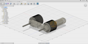
My research into this project began with understanding exactly how a stirling engine works, and the physical orientations that were possible when it came to designing the structure. There are multiple orientations for the layout of the pistons such as inline, side by side, offset, etc. I chose to do a side by side engine because it seemed like the most simple to design and offered the least amount of complicated pieces. Shown below is a nice looking stirling engine that has the same layout as the one I designed.

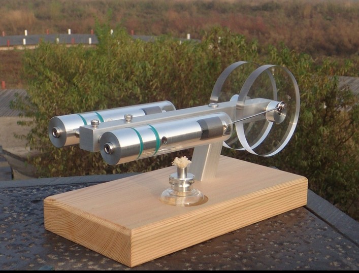
As you can see, the pistons are side by side, offering convenient support locations as well as easy flywheel design.

The main problem I encountered while designing the engine was trying to come up with a suitable material for the pistons. Since a flame would be used to heat the air, I couldn’t 3D print the pistons as they would melt under the heat. After much research, I noticed that a lot of home designs used these   borosilicate glass syringes as the work and displacer pistons. They are perfect for heat resistance and also offer the air-tight property that is needed for a stirling engine.

The build

Unfortunately, I did not take pictures of the pieces as they were being printed because I was just too excited to put them all together. IMG_20160502_243116473

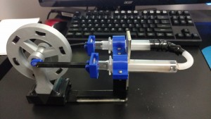
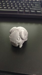
This is the finished engine, in all its glory. Unfortunately, the glass tip of one of the syringes broke off when I accidentally dropped it, so some tape was needed to attach the silicon tube to the end of the piston. Also worthy of noting is the metal L-bracket that is attached to the engine. I neglected to account  for the strength of the support connecting the flywheel to the pistons, and the whole engine tends to flex as a result. The L-bracket prevents the bending from getting too severe.

Success (or lack thereof) and future work

To my disappointment, the engine does not work, the finished product should function something like this. I suspect that the issue is that I have made the displacement volume too much for how little inertia the flywheel provides. When the engine would be operating, a small low pressure environment should be created between the two pistons, however the force that this creates on the flywheel is too much to allow it to smoothly run between cycles. To correct this, I need to shorten the distance that the crank arms are away from the center axle, and possible make the flywheel heavier. Some other modifications I will make is thickening the base to prevent flexing, and sink the screws in the base to make it a flat surface.

Week 10 – CU Fab Lab

Sadly, this was our last experience at the CU Fab Lab. Even more sadly, I was sick for our second visit and so this was only my second time going. However, I got to work with arduinos this time, and since that is something that I have always wanted to do, I was very excited. Actually, working with arduinos is basically the type of work I hope to go into after graduating. Being able to work with my hands and physically build something while also being able to use my programming knowledge is how I describe my dream job.

A lot of what we did on Monday was just to understand the basics of the program and the types of things you can do with arduinos. We talked about controlling LEDs, Using variable resistors, and controlling a servo. It seemed like a lot of people had trouble not with the actual board but with the coding, which is understandable for people who have never experienced programming. I tried helping those around me with some of coding, since I knew a bit about the language we were coding in. It was a really cool experience, and I was even able to combine all of the little projects we did into one big contraption using the variable and touch resistors to control the servo and the led at the same time.

Towards the end, we talked about creative ways to use some of the things we had learned, including making a big touchpad out of aluminum foil. After seeing an arduino firsthand after I’ve heard so many things about them, I think I am fully convinced to go out and buy one for myself so I can continue playing around with it and hopefully do some #digitalmaking in my freetime.

Semester Project

For my semester project I decided to make something that I’ve always been interested in making, but never had the proper resources: a stirling engine. A stirling engine is a engine that draws its power from a heat difference, usually a flame. I won’t go into the physics of it, but here is a nice gif of the process. It’s a relatively simple concept, and there aren’t a lot of complex parts, which makes me think this would be a great project. For obvious reasons, having an open flame creates some design obstacles when it comes to meltable plastic. I’ve been doing some research, and to my surprise this isn’t an uncommon thing for people to make with 3D printers and some pretty clever designs use glass medical syringes for the work and displacement pistons. Since it would be very hard to find some airtight seals on parts that must withstand high heat, I think I will be borrowing this idea. With that out of the way, the majority of the rest of the work will be modelling the supports and pieces in fusion 360. Since there will be moving pieces, I will be purchasing some ball bearings and face some design challenges incorporating them into the build. I also need to do a little math to figure out the right displacement and dead volumes for the actual physics of the engine. Overall, I am very excited about the project and hopefully my engine will actually work and not just be a paper weight.

Week 9 – Build a Printer Event

As you all know, this week we all took part in the Build A Printer Event in the Bif Atrium. Going into it, I didn’t really have any expectations for the event. I wasn’t excited nor was I really dreading it, I was kinda just “meh” about the whole thing. I’ve put some things together in the past, ranging from simple IKEA furniture to a whole Dark Matter experiment at Fermilab, but a lot of those endeavors were solo operations, I have never built something with a group of people, let alone a class of 30. But honestly, I really enjoyed the event.I worked on putting together the extruder with a couple people for a majority of the event, and once we had finished that we moved on to helping with the Z-stage. There was one point where two of us were hammering away at pieces on the floor to try and make as little noise as possible so that we didn’t distract people studying in the atrium. It must have been a funny sight.

We got hung up at a certain point, as we couldn’t find a little wooden piece that we needed. There were supposed to be 4 of these tiny wooden spacers and we could only find 3. So in the spirit of #digitalmaking, we decided to run upstairs to the makerlab and 3D print our piece! I quickly modeled the piece in Fusion 360 from measurements of the other 3 blocks, and we did a quick 3 minute print of the piece! Unfortunately, I was so wrapped up in the build that I neglected to take pictures, but the piece came out great and should work perfectly in place of the missing piece.

The build ran a little long, so a couple of us stayed after to finish up individual sections before packing away the rest of the pieces to be put together later. All in all, it was a great event, and I thoroughly enjoyed it, not to mention got a sweet maker t-shirt out of it. I would definitely say that in addition to the build process, I learned a lot about how the extruder mechanism and FDM printing as a whole work. I Hope someday that I am lucky enough to be able to afford one of these kits for myself, I would love to have 3D printing continue as a hobby after I graduate this may.

Week 6: CU Fab Lab

This week we all got the amazing experience of exploring the Champaign-Urbana fab lab! The lab itself is awesome, decked out with a whole range of machines and utilities to help just about anyone make just about anything. I am upset that I only found out about this amazing place so late, or else I would have seriously considered working there.

After the tour, I broke off with the group doing the laser cutting, although I really wanted to check out the arduinos. The software we used to create our images to be cut is called Inkscape, and it was actually really intuitive and easy to use. The software that controls the printer just takes a black and white pdf of your cut, which I thought was really interesting. The thickness/darkness of the lines determines the laser strength, and thus determines whether you just raster (scratch the surface) or vector (cut all the way through). I decided to raster an image onto clear acrylic, because I have seen people online do some cool things with etched acrylic and LEDs.

 IMG_20160306_171954604

This is what I ended up with after the laser did its thing. I think it turned out really well, and I am going to be 3D printing a base for it, so that it will stand up straight. I’m going leave space for an LED and a battery bay in the base, so that when the LED is on, the light will shine up through the clear acrylic and reflect off of the rastered image (hopefully) and make it look like its glowing.

I am definitely going to be coming back here in my free time and I cant wait for this week when we get to revisit the fab lab and check out some more interesting tools!

Week 5 – 3D modelling with Fusion 360

These past 2 weeks were a lot of fun for me. I have been using 3D modelling software for a couple years now, and Autodesk has by far the best products. I learned AutoCad and Inventor in high school, so fusion 360 was really easy for me to get the hang of because its essentially just Inventor with a whole lot of bells and whistles. To refresh my memory, I chose to model the bolt. Yeah, it was probably the easiest design template to pick, but I felt like it had all the basics: chamfers, fillets, extrudes, revolutions, etc. bolt

I definitely noticed that I am much more comfortable with the parametric modelling than the free form stuff. Something in me just doesn’t like eyeballing or grabbing and pulling the free form designs. Because of this, I was very grateful for our art and design mentors as they seemed really comfortable with the free form modelling.

In the spirit of shaking the rust off of my 3D cad skills, I thought it would be nice if I made something for my friend who is coming down to visit this weekend. The picture below is my 3D model of a logo for a team that we are both big fans of.

c9 logo

I have also started thinking about my semester project. I am currently torn between two ideas. Im either going to make a Stirling engine, which is just a fancy candle-powered wheel, or an audrino powered rotating LED display. The Stirling engine is definitely more 3D printer dependent, so I have already started modelling my design for it. Here is what I have so far:

stirling engine

I’m really looking forward to being able to use this software that I know with my brand new knowledge of 3D printing to make some really cool things!

DFA WorkShop – Week 3 Reflection

What

This week we worked with the Design for America RSO. They gave us a crash course on the process behind designing, complete with a  “Use your body to make letters” team building exercise. We also worked in small groups to brainstorm and design some solutions to everyday problems facing some blind individuals in Austin, Texas. My group and I chose to tackle the obstacle facing a semi-fictional blind mom, Rose. Rose needed to be able to keep track of her child while they played at the playground. We came up with a number of solutions, most notably was a wearable device that allowed Rose to communicate with her child.

So What

I’m going to be honest here, the DFA workshop felt like more of an empathy workshop than a designing one. Of course, there are so many problems that affect people on a daily basis, and our friends at DFA are doing amazing things to help these people everyday. That’s what the organization is all about: Designing for America. But I feel like there is a little more to the whole design process. I don’t think there was a huge global need for iPhones, or a rocket to the moon. To me, the coolest designs are the ones that we didn’t even know we needed, or we designed just because we could, or simply to push the envelope of whats possible. However, I do think that the core of their workshop holds true not just for designing, but for anything. I’m simplifying it a little, but basically DFA’s approach to designing was: Think about the problem/obstacle, brainstorm solutions, discuss with your peers, chose the best solution.

Now What

One thing that I took away from the DFA workshop that really stood out to me is how many great ideas were presented by our classmates. From the smart-glasses to the drink protector, to the topographical tablet, there are so many inventive people in this class. I cant wait to work with all of you and make some really cool things.


Week 2: First Steps into the world of 3D printing

So this week was the first time ever using a 3D printer for a lot of us. I cant help but be surprised by how easy and intuitive it was. The whole process, from finding exactly the right 3D model on Thingiverse, to importing it in Cura, to starting the print on the actual printer was incredibly user-friendly and not nearly as intimidating as I had imagined it would be. I chose to print a figurine from the video game League of Legends. IMG_20160207_124234412

It came out so great that instantly I knew I would be coming to the makerlab all of the time to print out small things for around my apartment. I have already printed out some things for my roommates, and my other friends already have little figurines or gadgets that they want me to print for them.

After browsing Thingiverse and Shapeways I have bookmarked a few items for around my apartment that I could definitely see myself taking advantage of.

The first is this desk hook from Thingiverse. I have been trying for months to Macgyver a hook to hold my headphones, with little success. I would have to alter the design a little to accommodate the size of the headset, but this is definitely something I can see myself printing.

The next is a simple bottle opener. My roommates and I are always talking about how difficult it is to use our bottle opener. So why not 3D print one? I’m not sure about how strong the material is though, and whether or not it would break if you encountered a stubborn bottle cap.

Over the summer I built my first desktop computer, and along with it I bought my first mechanical keyboard. I have wanted to get some cool keycaps for it, but I am always deterred by the price. However, I found this spacebar keycap and made me realize that I can just print my own keycaps! The only thing that worries me about printing keycaps is the texture of the plastic. I’m not sure if it makes for a great keyboard key.

The last item I looked at was a phone case. I recently got a new phone for Christmas, and I have been debating on getting a case for it or not. I am reluctant to because the back of the phone is wooden and it looks amazing, I wouldn’t want to cover it up with a case. However, I saw some other people printing some phone cases on Monday that had these cool designs where the back wasn’t a solid piece. That could be perfect for me. While I have no idea what “City of Heros” is, which apparently is the theme of the case I linked, I could hopefully alter the design to something I like.