Design, ideas, progress, challenges, and workarounds for my semester project. Part 3 of 5.
Part 1: Time for a semester project?
Part 2: Progress through time
Part 3: Tick tock goes the clock (this post)
Part 4: What’s in a face?
Part 5: Closing Time
Prototype 2.
Simplifying circuits is how I’m going to fix things. Prototype 1 tried to incorporate 2 colours of LEDs, with only 12 IO points. Simplifying the design, I’m reverting to a single colour of LED, which does not call for the circuitry to be as complicated.
circuitry works! Just the code to rewrite now then.
The LEDs can light much brighter in this configuration, so i can have greater spacing in my clock face and go for a bigger frame.
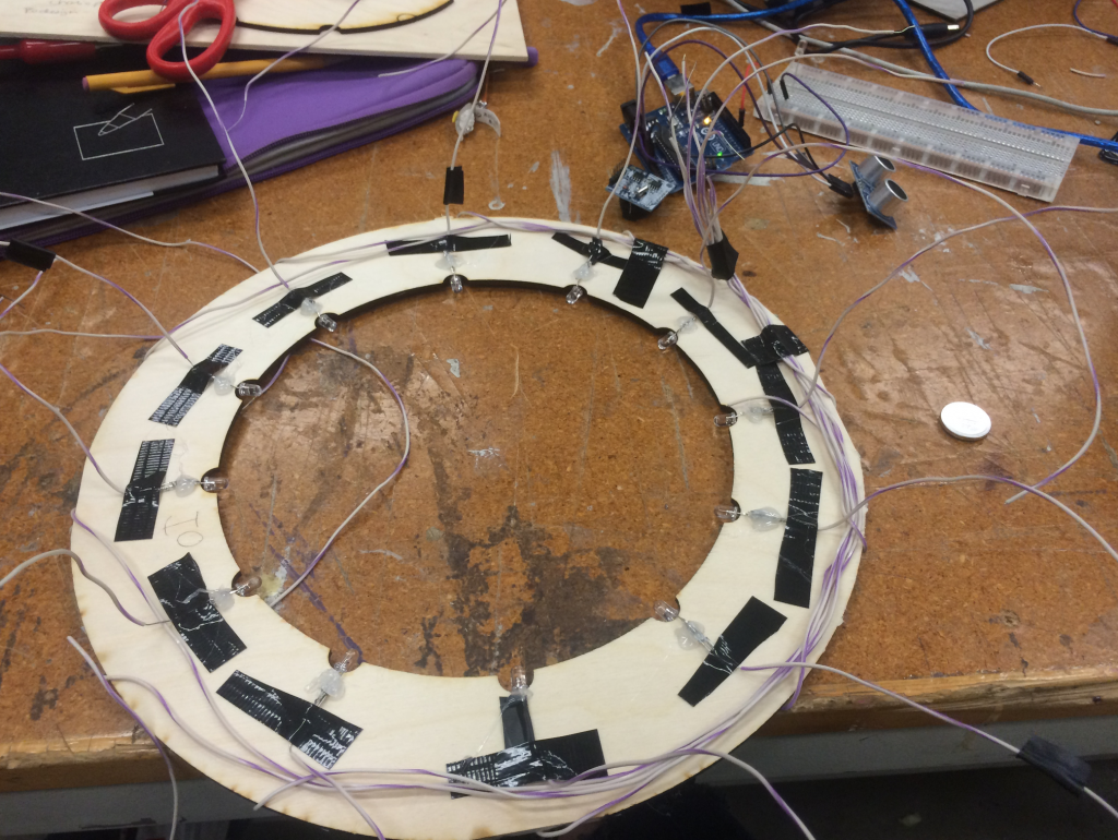
working on framework of prototype 2
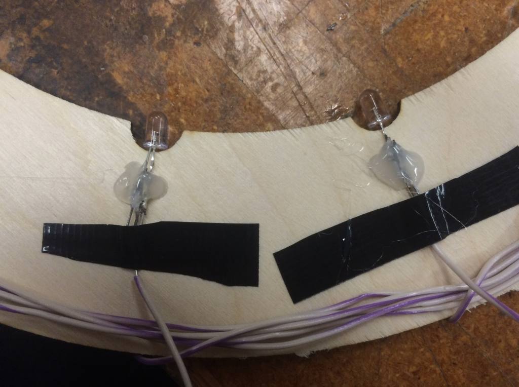
Detail of LED positioning
A little spanner in the works at this point: the time code stopped running on the device. With a lot of help and troubleshooting, the problem was located as a dodgy connection in the hardware, not a code issue as originally expected.
Coding shenanigans
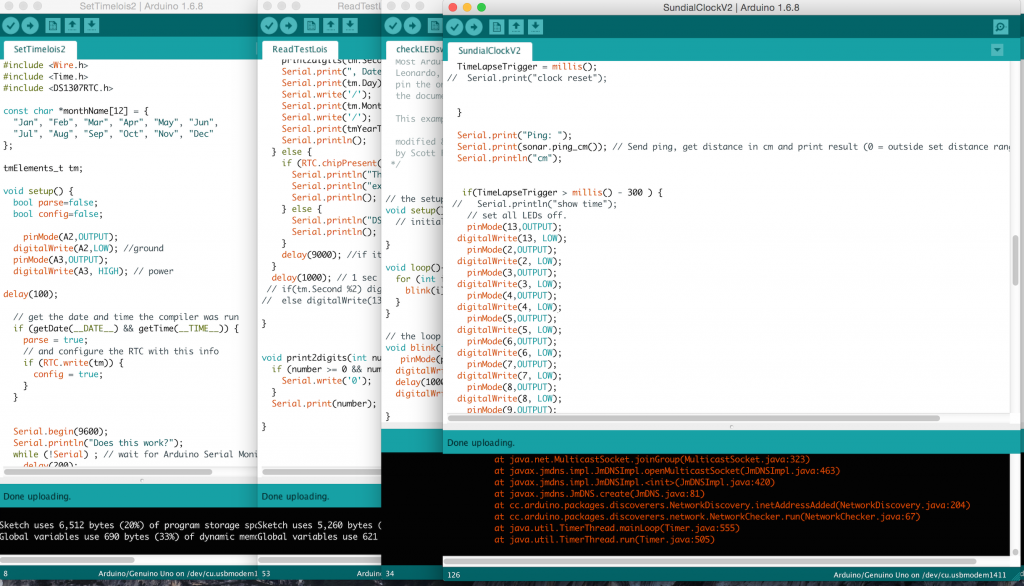
Editing code
My code has also been through a series of iterations. It requires 3 files to be run:
- setting the time on the time device to sync with my laptop
- reading and checking the time on the time device
- running the LED commands based on the time on the time device
.
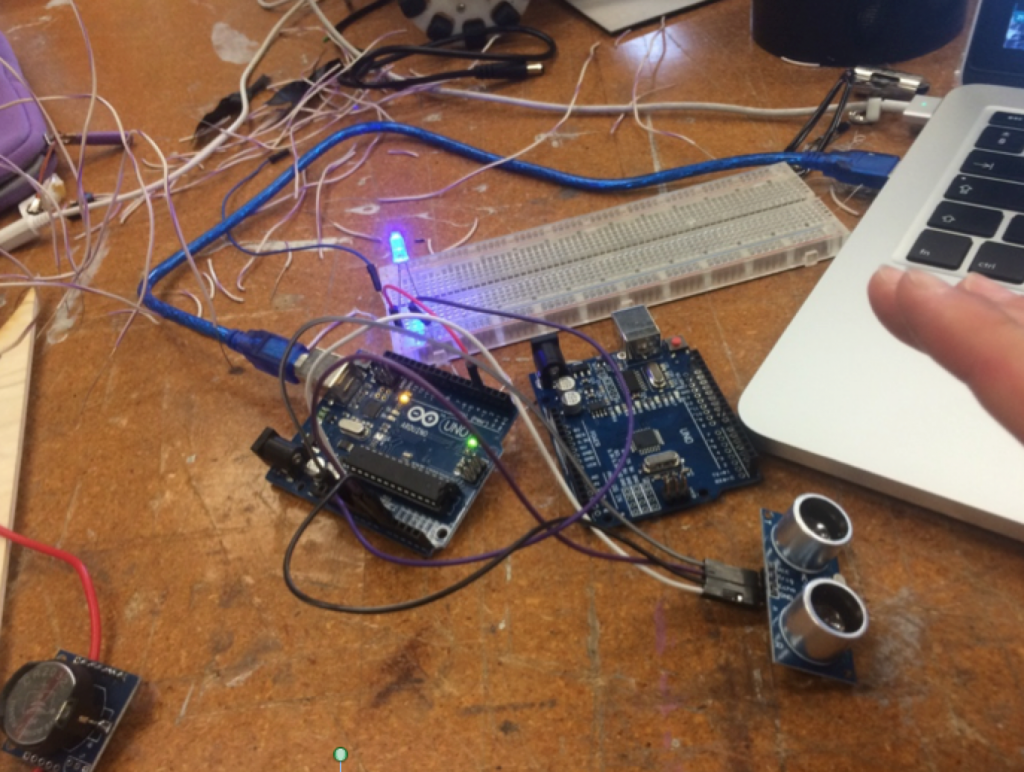
Since I couldn’t utilise 2 colours of LEDs, I’ve opted to include a proximity sensor to detect when the time is being checked. The design is now that it only becomes a clock when the sensor is triggered. For the rest of the time, its a light installation.
Heres the testing of the proximity sensor:
Note how the shadow cast by the pencil makes the hands of the clock and tells the time
Pingback: cialis over counter at walmart
Pingback: ivermectin 12 mg for sale