(return to main navigation menu)
Design, ideas, progress, challenges, and workarounds for my semester project. Part 2 of 5.
Part 1: Time for a semester project?
Part 2: Progress through time (this post)
Part 3: Tick tock goes the clock
Part 4: What’s in a face?
Part 5: Closing Time
Realistically, there’s 2 routes I can take with creating a timepiece. Predominantly mechanical, or predominantly electrical. Cogs and wheels or LEDs and circuits?
Progress milestones and challenges:
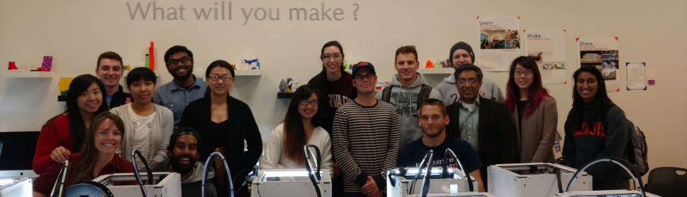
early design and prototyping days
- I started off by brainstormed ideas for a clock design that would utilise many making techniques.
Fixed design
- With my love of the outdoors, the way the world works at the most naturalistic level, the fundamental equations and the beauty that can be seen through them, I feel that merging old time-telling techniques with modern techniques is a particularly fitting final project for me.
- In the brainstorming process, Vishal suggested some form of interactive nature for the clock. I originally thought about proximity sensors to activate a screen displaying data or something (as an additional feature besides time-telling). The idea that I’m running with is that I want to keep a simple elegance about the design, in keeping with the simplicity of the concept. No need to clutter it with unnecessary features for the sake of making it sing and dance.
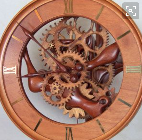
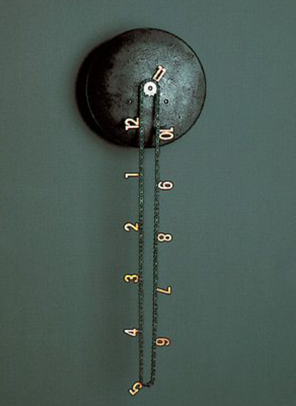
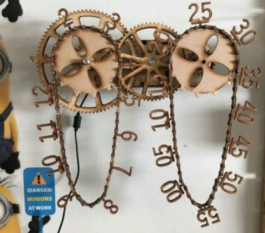
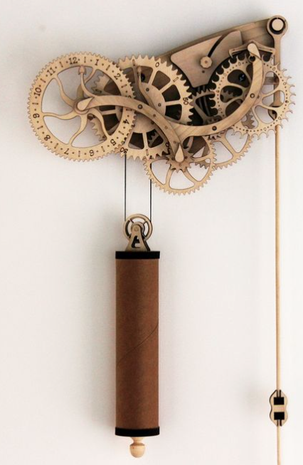
Looking at various mechanical designs as inspiration:
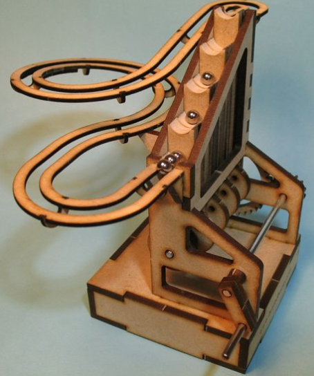
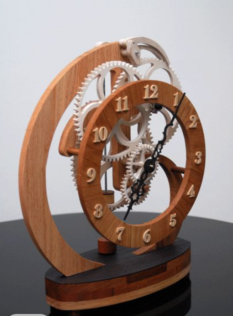
.
- At first I printed some gears to see how feasible it would be to produce a mechanical-based clock.
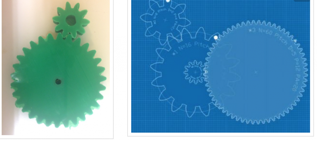
Playing around with gear design and 3D printing gears
I found that the gears did not mesh well, and that it would be difficult to get smooth motion out of this.
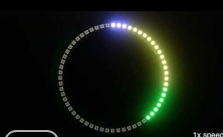
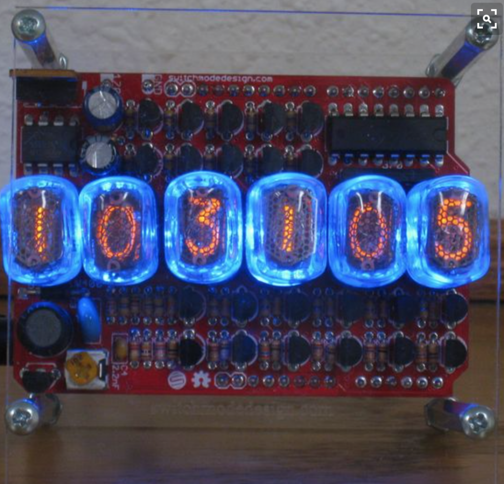
I then considered possibilities with LEDs and circuits:
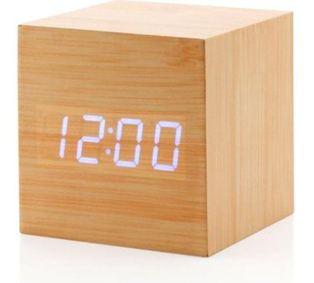
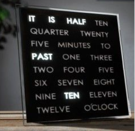
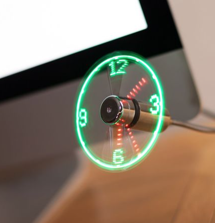
Different design approaches for LED clocks
.
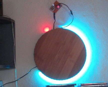
Settling on an idea:
- What I’m creating is a a clock face that relies on shadows to be the hands of the clock. Different LEDs in a ring will light based on the time, and shadows cast by those LEDs will show the time.
- A similar concept was created as a design project in germany
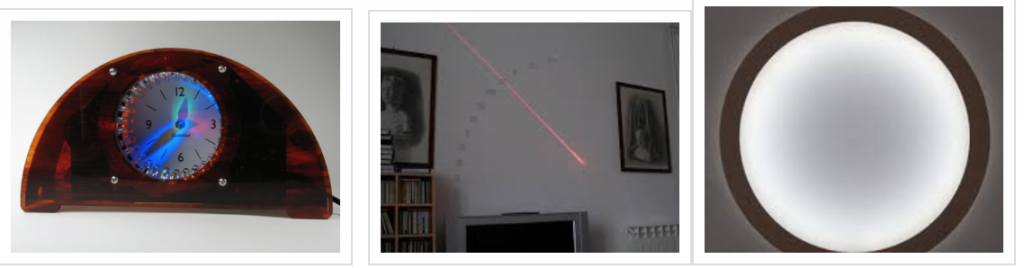
concepts that i want to play around with
.
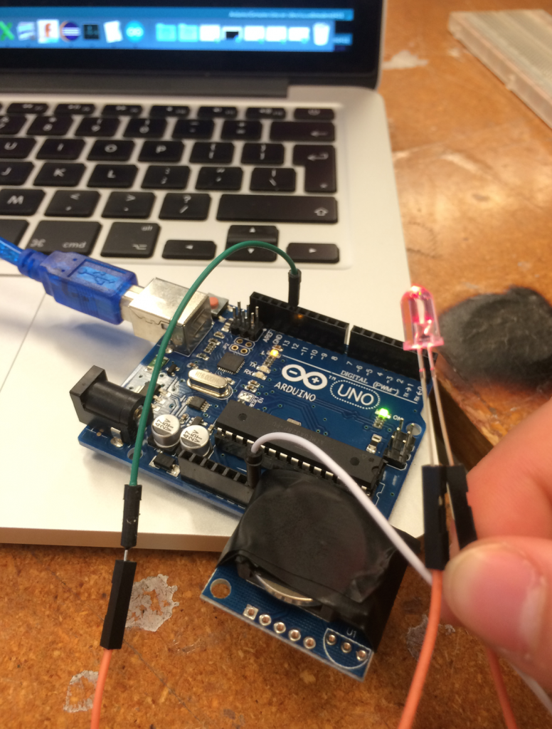
I got a time-keeping device working and talking with the arduino after some code bashing attempts. I’ve also managed to write some other code for the lighting of specific LEDs based on the time it reads from this device.
It utilises 2 rings of LEDs, with 2 separate colours. With a single arduino, its only possible to have 12 positions for LEDs. For more LEDs (ideal would be 60), a much more complex circuit would be required, with the use of charliplexing and many more man-hours of soldering and complexity.
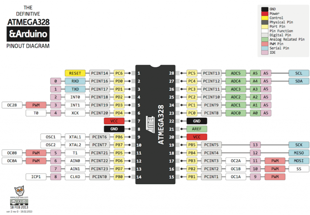
From this diagram I can see that theres only 23 I/O pins, so my design is constrained to that
.
Working with the limitation of 12 IO pins on the arduino, I developed circuitry where each position has 2 LEDs in series wired like so:
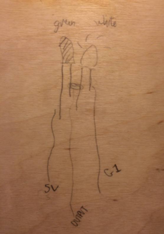
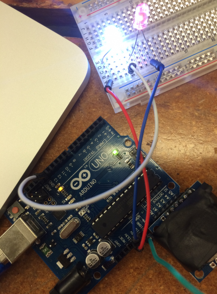
The concept works on a breadboard. While a low power is constantly running through, so the LEDs are low lit when not engaged, when the LED is chosen to light, it is significantly brighter than the others.
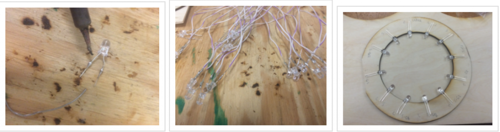
During the soldering process
.
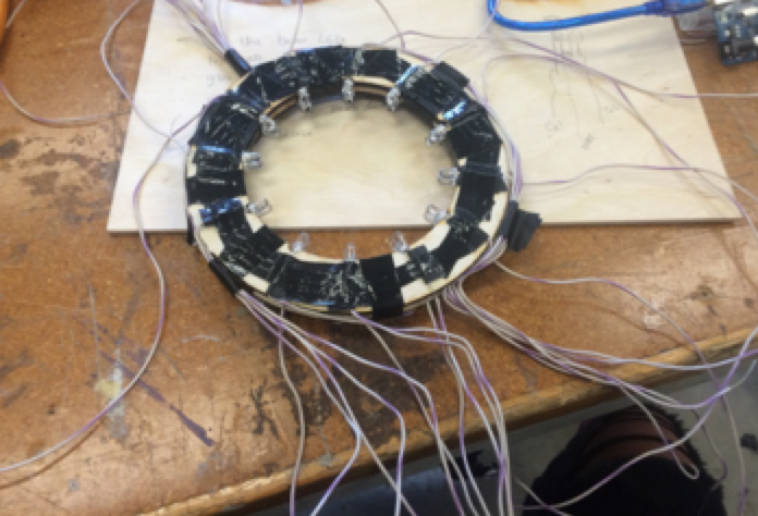
The parts are all soldered here, and wired up for testing. Unfortunately, with so many LEDs in the circuit, I found that the LEDs that should light brighter than the others do not have enough power to do so.
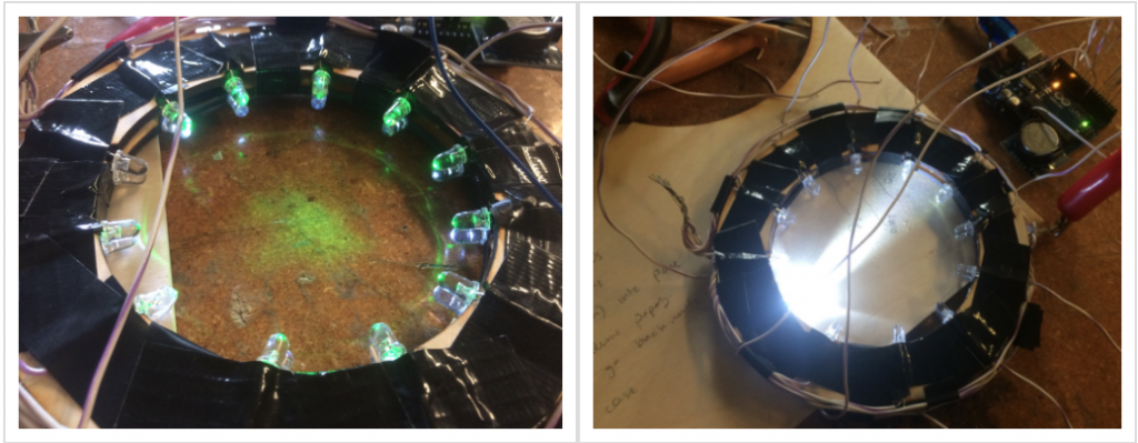
Testing the LEDs
Back to the drawing board.
Pingback: order ivermectin 12 mg