Week 12: Auditing our Design

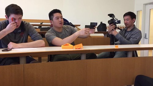
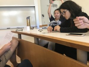
This week, we took a break from actually working on our prototype, and stopped for some constructive criticism on it. Professor Vishal assigned each team to another team that was similar or used similar ideas/ materials in their project. The teams sat down with each and provided an overview of the current design, and how it was currently functioning. The team that was critiquing would ask about the design, the issues that needed to be resolved, and other questions as well.

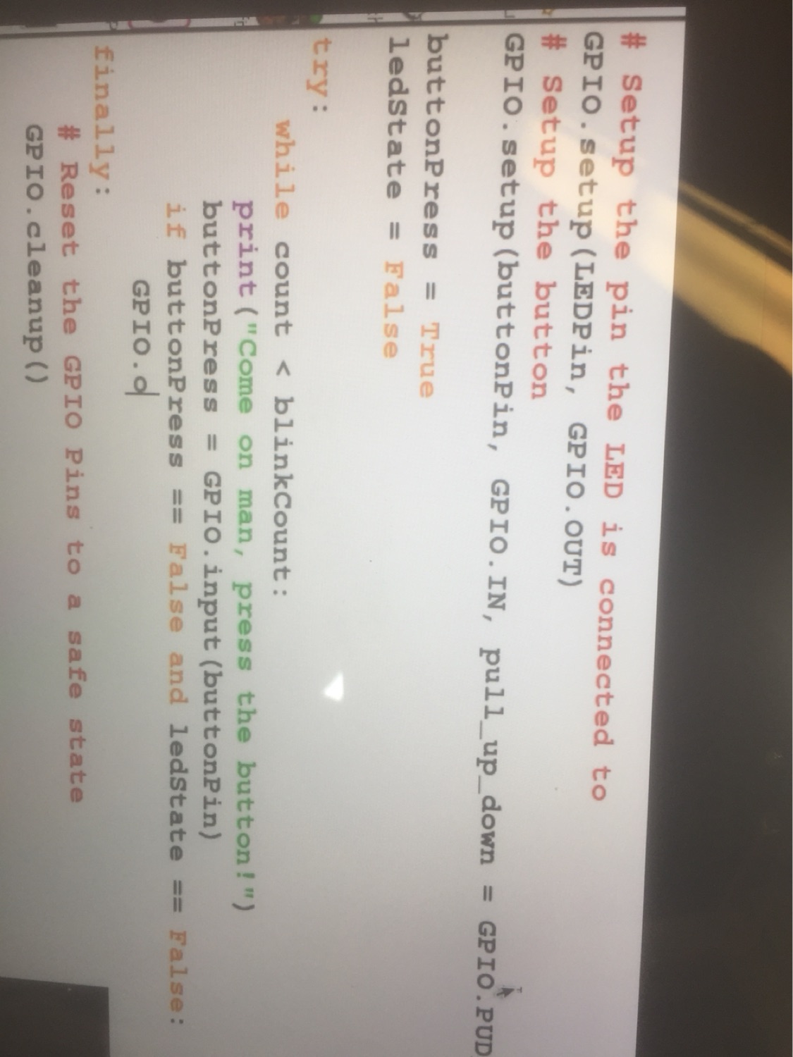
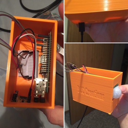
Our team was evaluated by JJJ Inc. They realized that our design was very complex, and overall they didn’t have a lot of suggestions for us. They understood that our prototype was already on track. However, they did suggest we should keep our ultrasonic transducer would be better than a button because an ultrasonic transducer would be more interactive and impressive. Our team was also evaluated by Professor Vishal. Professor Vishal told our team to focus more on the internal hardware versus the outerwear. Although Taofik is the one managing and coding for our project, Professor Vishal pushed and encourage Tiffany and me to understand the terms and functions of each of the technical components within our droid/bot.

After the evaluations, we continued to work on our projects. Many of the suggestions that both parties pointed out were important and logical. Obviously, as a team we need to take these suggestions into consideration and figure out if we will use these suggestions.

Wrapping Up

As we near the final presentations and showing off our final designs our team is assembling all the parts needed to finish our aquaponics model. We’ve been working towards creating functional pieces for the modular plant holders. Last week we finally finished a final design that we think will work well for holding the plants above the fish tank. Kenny and I also worked on creating the actual fish tank for the fishes. The acrylic just came into the Fab Lab so we paid them a visit to try and cut out more of the sides. The visit was very successful as we were able to print out a couple of the sides for our project.

After that we began working on 3D printing a tubing that will help connect our own fish tank to the tube that will run through our modular plant holders. That in itself wasn’t too difficult. We also designed a spout for the water to come out of the containers into our modular plant holders.

Kenny and I also began shopping for prototype fish containers in case we wouldn’t have the final acrylic fish tank ready. We purchased a plastic bin from Wal-Mart to substitute in and hold our fish/water. This will be useful in testing before we work on sealing a whole fish tank. We’ve also begun looking into what type of fish to get as Kenny will be keeping the fish tank to take care of it after we’re done with the project and the semester. Our team also began shopping for vanities for the fish tank to make sure it has a good aesthetic appeal. We bought some blue stones that should give the fish tank a good look. We’re also looking to get some good pebbles that will fit our design for the modular plant holders.

Feedback, Prototyping, Feedback, and more Prototyping progress

This week I learned the absolute cruciality of giving and receiving feedback. Through all prototyping processes whether that’s design thinking to agile software development to new product development, rapid prototyping success is contingent on the “rapid feedback-ing”. As Marty Cagan testifies in Silicon Valley Product Group’s Prototype Testing, “testing your ideas with real users is probably the single most important activity” in the prototyping process: and I honestly couldn’t agree more. This week we were lucky enough to receive feedback from Team AquaPonics as well as provide feedback for Team AquaPonics. Here is a clip during our feedback session between the two teams:

IMG_5469

Team AquaPonics gave us some great ideas and they were as follows: 1. To create a much stronger structural base. 2. Minimize the vibration the stopping component of our doorstopper experienced. 3. Utilization of either a stronger adhesive or multiple command strips on our prototype base:

Stronger Structural Base

Team Supra realized that dimensions of our prototype structural base had to be increased. By increasing density levels and overall dimensions, Team Supra’s doorstopper would not only have more surface area and density to absorb the initial contact shock from the slamming door but also have more areas to allow for structural fixing through command strips.

Minimizing Vibration

Team Supra decided to minimize vibrations by placing a bar that would allow for snug sliding of the stopping component of our doorstopper. Additionally, this bar would ultimately prevent all further torque that would be generated from door slamming vibrations ultimately allowing for doorstopper stability. Lastly, Team Supra has decided to employ a flex-plastic material allow for shock absorption.

Stronger Adhesive

Team Supra has decided to continue testing with command strips. However, instead of employing one command strip Team Supra will now be taking advantage of the greater sized and stronger structural base.  Team Supra will be placing command strip at optimal points of shock absorptions calculated through comprehensive testing. Multiple command strips placed at optimal focal points will ensure Team Supra’s door stopper a success.

Lastly, Team Supra created a post-consumer experience survey for testing subjects and participants to complete. Team Supra unfortunately had two prints fail in the lab this week. And due to high demand of 3D printing because of many final architecture projects, Team Supra will have testing completed by Tuesday at midnight. Thus, Team Supra is ready to see and hoping for some great results!

Auditing, Testing, and a Trip to Chicago

IMG_1571

As we quickly approach the end of the semester, our teams have started to refine our prototypes. This week in class, we split up into our teams and met with other teams for a design audit. Meeting one to one with another team, one team described their product by explaining the problem it was solving, how it worked, and how to use it. Then, the other team would ask questions about why they made certain decisions while designing the product. Based on those responses, the team would then offer suggestions as to how to improve the design for the next phase. Our team audited a hydration sensor FitBit attachment, an aquaponics system, and a doorstop. With each rotation, we were also able to receive feedback on our design.

While there is not too much we can change about our design, we did receive some valuable feedback. One student pointed out that printing the housing in white would make the security system more discrete as it would not stand out as much. Another student mentioned that she thought that students may forget to plug in the device before leaving. Based on that feedback, we will print in white when we finalize our design, and we are looking into incorporating either an on/off switch or activating the alarm remotely.

IMG_1596

Going forward, we had to now test the prototype. This Web Designer Depot page, though geared towards digital interfaces, still gives valuable insights into things to consider while testing prototypes. We came up with a list of questions to guide feedback and had a group member and a friend answer the questions after using the prototype in their apartment. We wanted to know how easy it was to use the design, any difficulties they found in their apartments, and any concerns they had about the product. Using this feedback, we hope to have the best product possible that could be brought to market.

IMG_1576

On Friday, Brian Xu and I had the opportunity to travel to Chicago with students from the Making Things class. We left campus early in the morning and arrived at Deloitte Chicago for a presentation and workshop. We were treated to lunch while learning about Deloitte’s Tech Trends and had a quick startup workshop on solving problems on our campus with a product that incorporated the tech trends. After running through the workshop, we headed upstairs to the Deloitte Greenhouse for a tour. The Greenhouse was designed for clients to come in and reach “breakthroughs” with problems they are facing in their firms. The Greenhouse incorporates different technologies into the space along with sensory equipment to enhance the experience. It was a really cool space to be in. After the Greenhouse tour we drove over to mHUB for a tour. mHUB is a unique space that allows members and partners to work together on learning, producing, and manufacturing. There was an incredible amount of equipment in the massive space and we were able to see some of the companies working on their products as we walked through. The entire experience was a great way to spend my Friday!

IMG_1581

Improving the Prototype: Value of Feedback & Testing

With a week to go before our presentation of our product, our class / team has been quite busy in the past week. Firstly, my team BCC creations have created a working prototype of our 3D printed security system. In terms of basic functionality our prototype works, and is being tested by our selves and friends of ours that can use it in their apartments on campus.

Addittionally in class we were able to get and give feedback on our existing prototypes. I enjoyed giving feedback to other teams prototypes as it was nice to hear other ideas that teams had. One group I gave feedback to was developing a wrist band that can detect when you are dehydrated. I thought this was a great idea, and I gave my perspective on how they can improve based on my experience playing sports and with recreation in general.

Our team also received extremely valuable feedback from the groups in our class. One group  had us think about the possibility of cats or pets  in an apartment, and if that would trigger our security system. Our security system uses an ultra motion sensor, which unless adjusted or installed properly would be triggered by a pet walking by.  Obviously if this was the case the device could falsely measure this movement as an intruder.  Because of this we have started thinking about creating instructions on exactly where users should install there device to monitor a door or window being broken into. Since in most cases we would not be able to install the product in a users home these instructions would be useful in making sure the security system functions properly. In our case the device should be installed high above or to the side of a door so that it is not triggered by other things around it outside of a door opening.

Secondly, our team was also given a suggestion that it may be easy for users to forget to make sure the security device is powered on. For example when a user leaves their home for an extended vacation or day or weekend, walking out of the home they could easily forget to set the alarm (power it on). This easy user error is something we are thinking about how to make our device easier to work around the users life style as opposed to the user working around the device. We have already programmed a message to alert the user when the device is on, and are considering other ways to make it easier to use the device,

Receiving Feedback

The feedback allowed our group to think about our product from a different perspective, and to also consider situations that we had not though of when we originally came up with the idea. The feedback helped us think of our device in a much more user friendly way. As our entire class starts to finalize our products, I can certainly say that the feedback and testing phase of the project has been the most useful in how informative it has been


Final Project Progress

This week was a good week where Team Xerott got hands on and made alot of progress towards our final project which is the Makerlab bot. We moved from just having a card board version last week to lasercutting the outer part thanks to my teammates Odelia and Tiffany. They used inkscape for designing the lasercut pieces to include the electronics in it.  Since this is our 2nd prototype, we used the laser cutting machine to create the two boxes (essentially these two boxes will become the body and head). The body was 120mm by 150mm by 120mm while the head was 135mm by 150mm by 120mm.Within the body, we engraved a heart, with a hole in the middle that was for the camera, and a cut out a square so that the user can see the LED display. The head has two eyes for the ultrasonic transducer (possibly, still debating if we have enough time for it) as well as holes on the side of its head for the speakers.IMG_0243
IMG_0240

IMG_0241

From there I was able to make progress on my part which is coding and putting together the electronic parts and Raspberry Pi. With the help of the Fablab, I was able to write code in Python on the raspberry pi operating system to activate the camera module that I got to work last week and allow a button to control this feature as well as an LED light to show that it is working. I have been working on getting it to interface with the LCD screen to display messages a s well in a form of subtitle for the bot. In the next couple week, we will need to know the specific measurements of every piece we have and finish are list of wanted utilities.
IMG_0204
IMG_0203
IMG_0202

Week 11: Continuing to Prototype

This week was simply dedicated to working on our prototypes for our final project. We made a lot of progress this week, and things are looking great! Some of our materials came in this week, so we got to begin testing out some of the parts that are going in our fish tank. While we ran into several problems throughout the day, we were eventually able to solve all of them and continue progress on our project.

The first problem presented itself within the opening minutes of class. Our teacher told us that our fish pump and tubes had come in, and we were very excited to try them out. Unfortunately, to our dismay, the hole for the tube to go into the fish pump was actually too large for the tube. We quickly reacted though, and got out some measurement tools and measured the size of the fish pump hole and the diameter of the tubing. We then used these measurements to create an adapter that would go into the hole but the other end would provide a snug fit for the tubing. This was the first time I realized how useful 3D printing could truly be firsthand. Before 3D printing, we would have been out of luck, and had to get new tubing, or searched for a pre-manufactured adapter. However, thanks to 3D printing we were able to get fix the problem within the hour, and continue progress on our prototype.

Once we had the tube fit snugly into the pump, we were able to test the pump out to see what setting we would need it on to get the flow of water that we wanted. After a couple tests we got it to the setting we want. A picture of our initial test is provided below.

IMG_0506

Finally, we capped the day off with sanding down the connectors on our plant containers to see if we could get them to fit. Last week, we printed the containers out, and the holes ended up being a little too small for our connectors. However, after a couple minutes of sanding, the connectors had lost enough material to be a perfect fit, and we were able to do a test run of the pump bringing water to the top container and letting it flow down to the lower containers. It was really gratifying to see our initial design and hard work come all this way to a working prototype.

I hope to continue making progress in this next week and finish our final design in the next couple weeks. I can’t wait to see not only how our product progresses, but how the projects of the other teams progress into awesome designs!


Getting There

It was time to get on with our project. The deadline is coming soon and it will be here anytime now. For the past couple of weeks, we have been focusing on testing and designing our prototype models. We have made two prototypes as of now and are ready to make our final model. Just to remind everyone, our product was the hydration wristband for a FitBit. The first prototype was a cardboard band prototype. That week even figured out the distance between the copper strips for the sensors. The following week we 3-D printed the band to check if the FitBit fits in the bumper or not. Unfortunately for us, we were unable to test out our band as the 3D printer could not print our design properly, the edge of one side of the band kept lifting up and we were sadly left with a strip of plastic. Additionally, we also made the copper circuit with all the wired soldered for the circuit.

This week we spent all the class time in the lab. I was working on the final model for the FitBit on Fusion360. This was the first time I was modeling a design that was designed by me completely. I couldn’t wait to see how it would turn out. I measured the actual FitBit charge 2 parts with a caliper to get the precise measurements so that I could make a perfect sized wristband which would prevent the screen from falling off. I then started printing it with the fully flex and the semi-flex materials. I realized that the flex material is hard to print with as I do not know the exact setting for it. However, to my surprise, the semi-flex material prints just like the regular PLA material. It was amazing to watch our self-designed wristband come to life. I guess my Industrial Design skills was put to test while modeling.

On Tuesday and Wednesday Ana and Ben met up at the FabLab to further work on the programming and moisture sensor. After these two sessions, our sensor is now able to do the following things:

  • Blink red 3 times, if the skin moisture is below average/dehydrated.
  • Blink blue 3 times, every 3 seconds (this will be changed to every 3 hours, as a this is an estimate of how often a person should drink a cup of water)
  • Blink green 3 times, if the skin moisture is too high, such as when a person is perspiring and losing water.

Please enjoy this video of me explaining what is happening with our sensor:

Approaching the Testing Phase

This past week was quite exciting for JJJ Inc. in a couple of ways. We were finally able to get the servo motor to flip the light switch. This is exciting for us because the servo motor we have (blue motor) is very small with only 1.2 kg/cm of torque. We ended up ordering a more powerful servo motor with 13 kg/cm in torque. As you can see, this new motor should not have a problem with moving the light switch up and down.

View post on imgur.com

View post on imgur.com

Now that we have the mechanism of flipping the switch up and down, we can go ahead and finalize the housing of the motor, possibly the Arduino board, and battery. This is where we run into another problem: getting the correct measurements of the housing that will allow us to mount the motor in the perfect location. We expect to have these calculations down this upcoming Monday so we can start 3D printing (possibly) the final housing prototype. Other than that, the code to controlling the Arduino is pretty much set. Implementing the Bluetooth module with the Arduino won’t be hard. What will be hard is putting everything together in the housing. For this reason, we might just run cables to the box and not have the Arduino or battery in the housing for the working prototype. Ideally, we would like to be able to fit everything into the smallest box possible.

Week 11: Moving Forward

This week was one of the biggest weeks in which results were finally tangible and felt like our project was actually leaping forward and taking shape. We went back to the FabLab to use what we learned during the workshops. Since this is our 2nd prototype, we used the laser cutting machine to create the two boxes (essentially these two boxes will become the body and head). The body was 120mm by 150mm by 120mm while the head was 135mm by 150mm by 120mm.

Within the body, we engraved a heart, with a hole in the middle that was for the camera, and a cut out a square so that the user can see the LED display. The head has two eyes for the ultrasonic transducer (possibly, still debating if we have enough time for it) as well as holes on the side of its head for the speakers.

There is definitely a lot of room to grow for our prototype. For example, the speaker holes could be shrunken by approximately 3 cm, and the depending on what kind of way we are going to start our droid, the eyes will also be extensively different. We approximated the area of each of these two parts and we’re planning to perfect the measurements as we continue further.

hile Tiffany and I were working on the specifics of the laser cutting, Taofik was programming the Rasberry Pi and connecting the breadboard and circuits to it.


As a Business major with not as much experience in coding or hardware, it truly is an advantage and positive to have someone that is an Engineering student on our team. One obstable we were presented with was that our 3D printed inside was warped because the layers were too thin, so not all pieces fit together perfectly. We are currently rethinking how we can prevent the warping from happening.

In the next couple week, we will need to know the specific measurements of every piece we have and finish are list of wanted utilities.