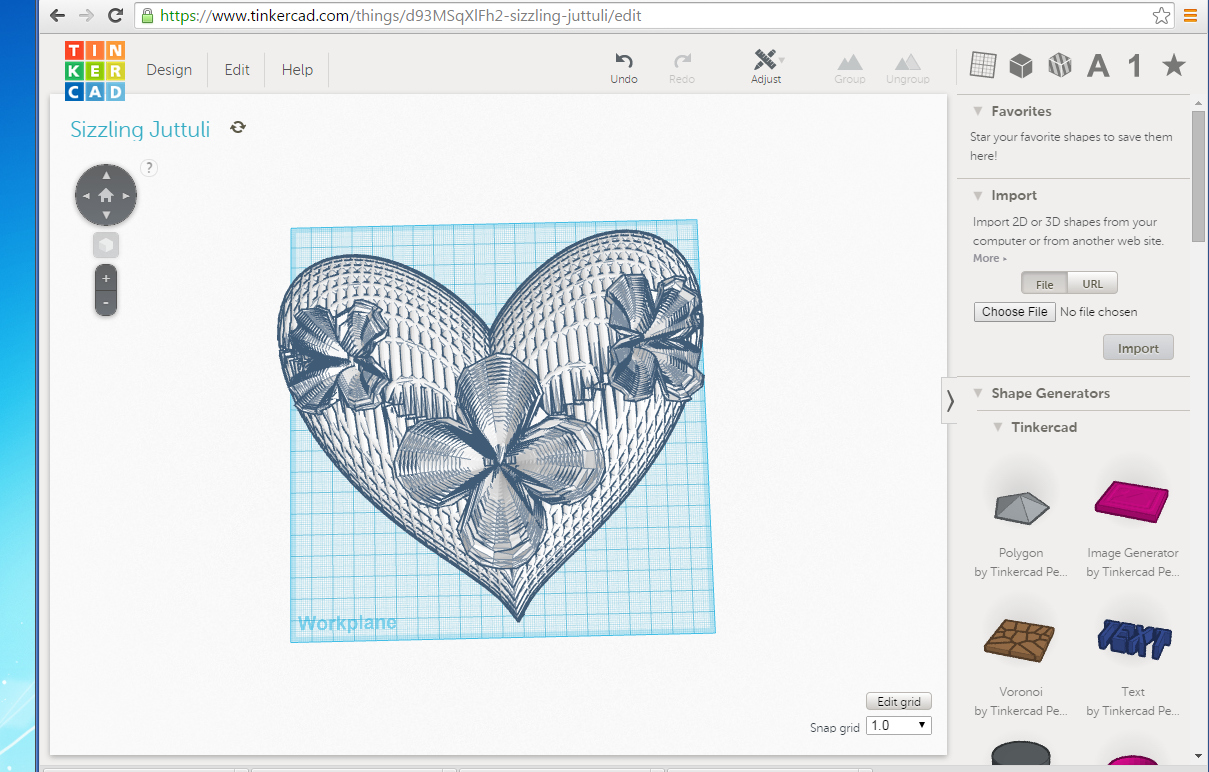
Heart and flowers modeled in Mathematica separately, then using MeshMixer to edit, scale and put them together.
This is also a part for my 3D printing project “Surprise Box”.
Update
1. The original file named “Flowery_Heart_Right_Size_2” is the basic concept of it, and although it looks nice, it is not printable on most of the 3D printers, because of several problems, like too many shells, the petals are too thin, etc.
2. The printable and updated version is named “ReallyFinally3stl_repariedsimplied”. This one has been cleaned, made solid, checked errors, strengthened and simplified. Therefore, this one is more suitable for printing. I will test it within a few days and put on the picture of the printed version here later.
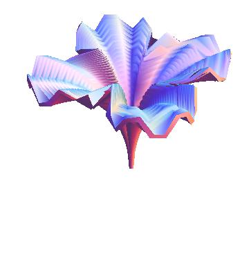
Also, since the original flowers were not suitable for printing, I changed the numbers of the formulas on Mathematica a little bit, and get some different shapes of flowers. (PS. If you notice, all the three flowers are different.) It is also interesting to disco(ver that when I change the power of one of the formula, I will be able to generate something that looked like a butterfly! Therefore, I added the butterfly on the new version! 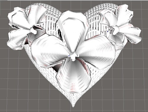 ( Original Version)
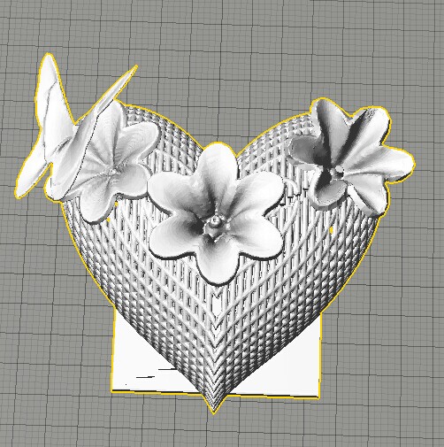
(Second Version)
In the process of trying to fix the problems, I learned a lot, like using new softwares like “MeshMixer”, “MeshLab” and “NetFabb”. I found these three very useful in different aspects:
1. MeshMixer is a place where you can edit and change your STL file, just like TinkerCad. However, MeshMixer is much more powerful than TinkerCad. For example, I failed to complete my edition of the flowery heart on TinkerCad, because it may be too complicated for TinkerCad. But I can do so in MeshMixer. Also, MeshMixer allow you to dynamically change the surface of the object, and provide functions like “make solid”, , smoothing, uniform scaling, and a lot more, which TinkerCad is not able to provide.
2. MeshLab is very useful for remesh the object. At first my STL file was ridiculously big, like 650+MB, which was very inconvenient because it slowed down my computer and I am not able to printed a file that’s huge like this. And usually, this problem can be solved if I lower my density of meshes, in another words, have a smaller amount of meshes. MeshLab gives you a function where you can simplify the model and reduce the meshes. It also shows you how many vertices and faces you have in your model. And by looking at these numbers, I was able to monitor the process of reducing faces amount, and chose the right level I wanted. This helped me to reduce the size of my file hugely, and finally get to a printable file of about 11MB.
(PS. I have an interesting discovery about decreasing the size of your file as well- If you get your STL file from somewhere else, like TinkerCad, MeshMixer, or from MakerBot Software after scaling it there, if you import the file in Blender or MeshLab, and then export it out from there, they will give you the minimized size possible for your current file!)
3. NetFabb (Basic) is a very helpful software too. It can help you fix the errors that your file may have automatically. Therefore, it can help clear up the printing errors before you put them to print!