Acoustic Impulse Responses for Wearable Audio Devices

This post describes our new wearable microphone impulse response data set, which is available for download from the Illinois Data Bank and is the subject of a paper at ICASSP 2019.

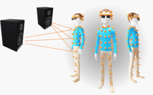
Acoustic impulse responses were measured from 24 source angles to 80 points across the body.

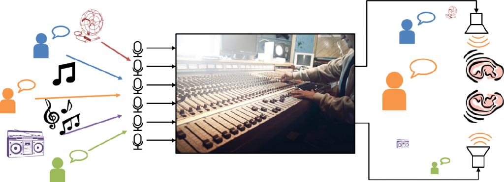
Have you ever been at a crowded party and struggled to hear the person next to you? Crowded, noisy places are some of the most difficult listening environments, especially for people with hearing loss. Noisy rooms are also a challenge for electronic listening systems, like teleconferencing equipment and smart speakers that recognize users’ voices. That’s why many conference room microphones and smart speakers use as many as eight microphones instead of just one or two. These arrays of microphones, which are usually laid out in a regular pattern like a circle, let the device focus on sounds coming from one direction and block out other sounds. Arrays work like camera lenses: larger lenses can focus light more narrowly, and arrays with more microphones spread out over a larger area can better distinguish between sounds from different directions.

Wearable microphone arrays

Microphone arrays are also sometimes used in listening devices, including hearing aids and the emerging product category of smart headphones. These array-equipped devices can help users to tune out annoying sounds and focus on what they want to hear. Unfortunately, most hearing aids only have two microphones spaced a few millimeters apart, so they aren’t very good at focusing in one direction. What if hearing aids—or smart headphones, or augmented reality headsets—had a dozen microphones instead of just two? What if they had one hundred microphones spread all over the user’s body, attached to their clothing and accessories? In principle, a large wearable array could provide far better sound quality than listening devices today.

Over the years, there have been several papers about wearable arrays: vests, necklaces, eyeglasses, helmets. It’s also a popular idea on crowdfunding websites. But there have been no commercially successful wearable microphone array products. Although several engineers have built these arrays, no one has rigorously studied their design tradeoffs. How many microphones do we need? How far apart should they be? Does it matter what clothes the user is wearing? How much better are they than conventional listening devices? We developed a new data set to help researchers answer these questions and to explore the possibilities of wearable microphone arrays.

Continue reading

What is augmented listening?

Augmented listening systems “remix” the sounds we perceive around us, making some louder and some quieter.

I am one of millions of people who suffer from hearing loss. For my entire life I’ve known the frustration of asking people to repeat themselves, struggling to communicate over the phone, and skipping social events because I know they’ll be too noisy.  Hearing aids do help, but they don’t work well in the noisy, crowded situations where I need them the most. That’s why I decided to devote my PhD thesis to improving the performance of hearing aids in noisy environments.

As my research progressed, I realized that this problem is not limited to hearing aids, and that the technologies I am developing could also help people who don’t suffer from hearing loss. Over the last few years, there has been rapid growth in a product category that I call augmented listening (AL): technologies that enhance human listening abilities by modifying the sounds they hear in real time. Augmented listening  devices include:

  • traditional hearing aids, which are prescribed by a clinician to patients with hearing loss;
  • low-cost personal sound amplification products (PSAPs), which are ostensibly for normal-hearing listeners;
  • advanced headphones, sometimes called “hearables,” that incorporate listening enhancement as well as features like heart-rate sensing; and
  • augmented- and mixed-reality headsets, which supplement real-world sound with extra information.

These product categories have been converging in recent years as hearing aids add new consumer-technology features like Bluetooth and headphone products promise to enhance real-world sounds. Recent regulatory changes that allow hearing aids to be sold over the counter will also help to shake up the market.

Continue reading

Tutorial 1: Simple Accumulator

Introduction

In this first tutorial we will create a design that will be able to increment or decrement a value by pushing buttons on the FPGA and displaying the hex value on the hex display on the board. This will cover combinational logic design, sequential logic design, and how to interface some of the peripherals on the FPGA as well as loading the design on the board.

Sequential vs parallel programming languages

Solving this problem with a microprocessor that executes instructions sequentially (like an Arduino) is pretty trivial to do. The code might look something like this…

/* PSEUDO CODE (will not compile on Arduino's IDE) */
while(1){
   if (button1){
      accumulator = accumulator + 1;
      while (button1) {}
   } else if (button2){
      accumulator = accumulator - 1;
      while (button2) {}
   }
}

Solving this problem in a hardware description language might not be so obvious. In SystemVerilog we are describing a digital circuit that will execute code in parallel. In order to achieve the same functionality as the sequential code from above we have to create a combinational and sequential logic circuit.

What is a combinational logic circuit?

A combinational logic circuit has a defined output based on all different combinations of its inputs – it’s kind of similar to a math function. Let’s consider an example of a familiar math function: f(x) = x^2. This function always has an output for any real value that is fed to this function: f(0) = 0, f(2) = 4, f(3) = 9, f(3.14159) = 9.8690, etc. In the digital world we can also have functions like this, but our inputs and outputs either have the value of 0 or 1. These functions are called boolean functions, and they are made up logic gates like AND, OR, NOT, NAND, etc. The link below covers the functionality of these logic gates with diagrams and truth tables.

http://www.ee.surrey.ac.uk/Projects/CAL/digital-logic/gatesfunc/

We can piece these logic gates together to create a combinational logic circuit and represent it with a function. Let’s create an XOR (exclusive or) circuit using AND, OR, and NOT gates. We will first create a truth table for XOR.

x  y | z
-------
0  0 | 0
0  1 | 1
1  0 | 1
1  1 | 0

This function’s output is 1 when X is 0 and Y is 1 (X’Y), OR when X is 1 and Y is 0 (XY’). If they are both 1 or both 0 the output is 0. We can write this function as z = x’y + xy’. The concatenation of two variables ‘xy’ represents the AND operation, the ‘ represents the NOT operation, and the ‘+’ represents the OR operation. Our combinational circuit looks like this.

That’s pretty neat, but how do we apply this to the problem we are trying to solve?

So now we know how to create a logic circuit, but how would we make a circuit that can increment and decrement a variable? We can start to think of what our inputs to this circuit would be: two different buttons on the FPGA – where one button will be the signal to increment and the other to decrement. We also need to think about how we can create something like a variable in hardware and how we can control what values it takes on. More specifically, we need to be able to have a way where we can remember what value our accumulator had and how our inputs to this circuit can control what values it takes on. To accomplish this we have to understand how sequential logic works.

What is sequential logic?

* Fill in detailed description *

Finite state machine design

Transferring your design into functional code

https://github.com/juanjm2/I-Vault-Blog-Code/tree/master/Tutorial_1

Quartus Tutorial

Actual FSM Behavior in hardware