Components
A subsurface drainage system consists of a surface or subsurface outlet and subsurface main drains and laterals. Water is carried into the outlet by main drains, which receive water from the laterals. Submains are sometimes used off the main drain to collect water.
The system will function only as well as its outlet. When planning a subsurface drainage system, make sure that a suitable surface or subsurface outlet is available or can be constructed. Where a surface outlet channel is used, all subsurface drains emptying into the outlet should be protected against erosion, against damage that occurs during periods of submergence, against damage caused by ice and floating debris, and against entry of rodents or other animals.
An older subsurface outlet used for a new subsurface drainage system should be free from breakdowns, fractured tile or crushed pipes, excessive sedimentation, and root clogging. It must be deep enough to intercept all outletting main drains and laterals and have sufficient capacity to handle the flow. It must also be deep enough to provide the minimum recommended cover for all drains newly installed or intercepted.If no suitable outlet is available and it is not practical to improve an existing ditch, you might consider using pump outlets. See the Pumping Plants section for a discussion of pump capacity and design and the Pump Specifications program for evaluating pumping requirements.
Site considerations
In planning a subsurface drainage system, you need to determine the topography of the site to be drained, keeping in mind the depth limitations of the trenching machines and the amount of soil cover required over the drains. The amount of surveying you must do to obtain topographic information depends on the lay of the land. Where the slope of the land is obvious, only a limited amount of data is needed to locate the drains. A topographic survey is necessary, however, for flat and slightly undulating land since it is not as obvious where drains ought to be located. Obtain enough topographic information so that you can plan the entire system before installing it. Planning the job without first gathering enough data often results in a piecemeal system that may eventually be very costly.
The type of subsurface drainage system you install depends to a large degree upon the soils in the area to be drained. Knowing the soil types also helps you anticipate special drainage problems. To identify the soils, refer to soil maps that are available at local offices of the Natural Resources Conservation Service and the Cooperative Extension Service. You can supplement the map information by taking soil borings and digging test pits. Once the soils have been identified, refer to the Drainage Guidelines section for drainage recommendations.
Also in planning a subsurface system, keep in mind that trees such as willow, elm, soft maple, and cottonwood should be removed for a distance of approximately 100 feet on either side of a subsurface drain line. All other species of trees, except, possibly, fruit trees, should be removed for a distance of 50 feet. If the trees cannot be removed, plan to reroute the line or to use nonperforated tubing or tile with sealed joints throughout the root zone of the trees.
Patterns
Because subsurface drainage is used primarily to lower the water table or remove excess water that is percolating through the soil over a general area, the drains are placed in a pattern determined by the characteristics of the area.If the soil is homogeneous, the water table is lowered at about the same rate on both sides of each drain. Flow from the drains is generally intermittent.
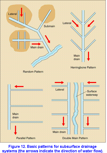
Four basic patterns are used in the design of subsurface drainage systems. Select the pattern that best fits the topography of the land, that can be located near enough to the sources of excess water, and that is suited to other field conditions. The four basic patterns are illustrated in Figure 12.
Random
The random pattern is suitable for undulating or rolling land that contains isolated wet areas. The main drain is usually placed in the swales rather than in deep cuts through ridges. The laterals in this pattern are arranged according to the size of the isolated wet areas. Thus, the laterals may be arranged in a parallel or herringbone pattern or may be a single drain connected to a submain or the main drain.
Parallel
The parallel pattern consists of parallel lateral drains located perpendicular to the main drain. The laterals in the pattern may be spaced at any interval consistent with site conditions. This pattern is used on flat, regularly shaped fields and on uniform soil. Variations of this pattern are often combined with others.
Herringbone
The herringbone pattern consists of parallel laterals that enter the main at an angle, usually from both sides. The main is located on the major slope of the land, and the laterals are angled upstream on a grade. This pattern is often combined with others to drain small or irregular areas. Its disadvantages are that it may cause double drainage (since two field laterals intercept the main at the same point) and that it may cost more than other patterns because it contains more junctions. Nevertheless, the herringbone pattern can provide the extra drainage needed for the less permeable soils that are found in narrow depressions.
Double main
The double main pattern is a modification of the parallel and herringbone patterns. It is applicable where a depression, frequently a watercourse, divides the field in which drains are to be installed. This pattern also is sometimes chosen where the depressional area is wet because of seepage coming from higher ground. Placing a main on each side of the depression serves two purposes: the main intercepts the seepage water, and it provides an outlet for the laterals. If the depression is deep and unusually wide and if you place only one main in the center, you may have to make a break in the gradeline of each lateral before it reaches he main. By locating a main on each side of the depression, you an keep the gradeline of the laterals more uniform.
Materials
Material specifications for drain conduits benefit both the drainage contractor and landowner. These specifications enable manufacturers to maintain uniformity in their products, thus giving buyers some assurance that the products will be strong and durable and perform adequately in drainage systems. The materials used for subsurface drainage include clay, concrete, bituminized fiber, metal, plastic, and other materials of acceptable quality. Current specifications for these materials can be obtained from the American Society for Testing and Materials (ASTM), 100 Barr Harbor Drive, West Conshohocken, PA 19428-2959 . The ASTM designations for these specifications are listed below. The Material Specifications program can be used to locate internet sites where the ASTM standards can be obtained. Use these or other federal specifications in determining the quality of a conduit.
| Material | Specification |
| Clay drain tile | ASTM C 4 |
| Clay drain tile, perforated | ASTM C 498 |
| Clay pipe, perforated, standard, and extra-strength | ASTM C 700 |
| Clay pipe, testing | ASTM C 301 |
| Concrete drain tile | ASTM C 412 |
| Concrete pipe for irrigation or drainage | ASTM C 118 |
| Concrete pipe or tile, determining physical properties of | ASTM C 497 |
| Concrete sewer, storm drain, and culvert pipe | ASTM C 14 |
| Reinforced concrete culvert, storm drain, and sewer pipe | ASTM C 76 |
| Perforated concrete pipe | ASTM C 444 |
| Portland cement | ASTM C 150 |
| Asbestos-cement storm drain pipe | ASTM C 663 |
| Asbestos-cement nonpressure sewer pipe | ASTM C 428 |
| Asbestos-cement perforated underdrain pipe | ASTM C 508 |
| Asbestos-cement pipe, testing | ASTM C 500 |
| Pipe, bituminized fiber (and fittings) | ASTM D 3356 |
| Homogeneous bituminized fiber pipe for general drainage | ASTM D 2311 |
| Homogeneous bituminized fiber pipe, testing | ASTM D 2314 |
| Laminated-wall bituminized fiber perforated pipe for agricultural, land, and general drainage | ASTM D 2417 |
| Laminated-wall bituminized fiber pipe, physical testing of | ASTM D 2315 |
| Styrene rubber plastic drain pipe and fittings | ASTM D 2852 |
| Polyvinyl chloride (PVC) sewer pipe and fittings | ASTM D 2729 |
| Polyvinyl chloride (PVC) pipe, Type PSM | ASTM D 3033 |
| Polyvinyl chloride (PVC) pipe, Type PSP | ASTM D 3034 |
| Corrugated polyethylene tubing and fittings | ASTM F 405 |
| Corrugated polyethylene tubing and fittings, 8 to 15 inches | ASTM F 667 |
| Pipe, corrugated (aluminum alloy) | ASTM B 745 |
| Pipe, corrugated (steel, metallic coated) | ASTM A 760 |
Clay drain tile
In ASTM standard specification C4, clay drain tile is divided into three classes according to its physical test requirements: standard, extra-quality, and heavyduty. Standard drain tile is satisfactory where the tiles are laid in trenches of moderate depth and width and where the tile will not be exposed to severe conditions. Use extra-quality and heavy-duty tile where conditions are expected to be severe. (Load requirements are discussed under the Design section.)
To be rated standard, clay drain tile that is 4 to 12 inches in diameter must have a crushing strength of 800 pounds or more per foot of length (Table 2 ). 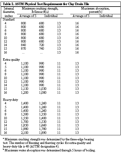 The tile must have an absorption rate not exceeding 13 percent for an average of five tiles. To be rated extra-quality, clay drain tile that is 4 to 14 inches in diameter must support at least 1,100 pounds per foot by the three-edge bearing test and have an absorption rate of not more than 11 percent. Heavy-duty tile has the same absorption rate as extra-quality tile but can support greater loads.
A few points to keep in mind about clay drain tile are that color and salt glazing are not reliable indicators of tile quality, that clay tiles are not affected by acids or sulfates, and that low temperatures normally will not damage clay tile, provided that it is properly selected for absorption and carefully handled and stored during freezing weather. To reduce chances for damage due to freezing, do not string out or stack clay tiles on wet ground during periods of freezing and thawing.
Concrete drain tile
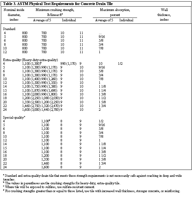
Concrete drain tile of high quality will give long and satisfactory service under most field conditions. There are four classes of concrete drain tile:
Standard-quality tile is intended for land drainage of ordinary soils where the tiles are laid in trenches of moderate depth and width. Tile of this quality is not recommended where the internal diameter is more than 12 inches.
Extra-quality tile is intended for land drainage of ordinary soils where the tiles are laid in trenches of considerable depth, width, or both.
Heavy-duty, extra-quality tile is intended for land drainage of ordinary soils where the tiles are laid in trenches of relatively great depth, width, or both.
Special-quality tile is intended for land drainage where special precautions are necessary – for example, (a) where the tile is laid in soils that are markedly acidic (pH below 6.0) or that contain unusually high quantities of sulfates, or (b) where the tile is laid in trenches of considerable depth, width, or both.
ASTM standard specification C 412 lists the physical test requirements for each of these classes (Table 3).
Plastic drain tubing
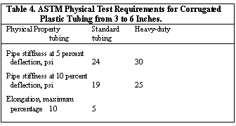
High-density polyethylene (PE) is the most commonly used material for corrugated plastic drains in the United States. Polyvinyl chloride (PVC) is more commonly used in Europe. ASTM standard specification F 405 contains specifications for 3- to 6-inch corrugated polyethylene tubing (Table 4). ASTM standard specification F 667 includes specifications for tubing that is 8 to 15 inches in diameter. Standards are being developed for corrugated PVC tubing and fittings intended for systems involving soil drainage and wastewater.
| Table 4. ASTM Physical Test Requirements for Corrugated Plastic Tubing from 3 to 6 inches | ||
| Physical Property | Standard Tubing | Heavy-duty Tubing |
| Pipe stiffness at 5 percent deflection (psi) | 24 | 30 |
| Pipe stiffness at 10 percent deflection (psi) | 19 | 25 |
| Elongation, maximum percentage | 10 | 5 |
Plastic tubing is not affected by acids and chemicals normally found in the soil at the drainage depth. Plastic may become stiff and brittle at very low temperatures or lose some of its stiffness when exposed to the sun on a hot day. But the sensitivity of plastic to temperature is a problem only while the tubing is being handled. Temperature ceases to be a problem once the tubing is installed and buried. If you install plastic tubing during unusually hot or cold weather, consult the manufacturer for advice on handling the tubing under those conditions.
Design
The purpose of drainage is to lower the water table far enough below the ground surface that it will not interfere with plant root growth. The degree of drainage required depends upon the maximum allowable height of the water table, the minimum rate at which the water table must be lowered, or the maximum allowable duration and frequency of ponding. The designer of the subsurface drainage system should select the degree of drainage that will fit the various crop requirements of the site.
Drain size
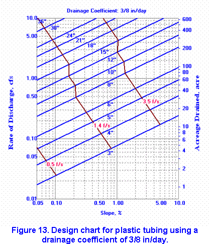
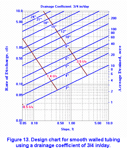
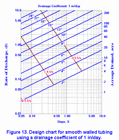
One of the first steps in determining drain size is to select the drainage coefficient, which is the rate at which water is to be removed from an area. It is a value selected to provide adequate drainage for future crops and is expressed in inches per 24 hours. Drainage design may be based on either steady state assumptions or transient assumptions .
Recommended drainage coefficients are given in Table 5. 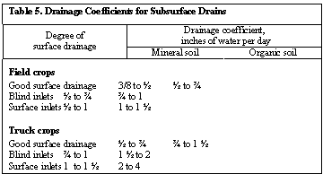 Where field ditches or watercourses provide adequate surface drainage, the drainage area for which you are choosing a drainage coefficient need only include the area that will be drained by subsurface drains. If the slope of the field is less than 0.2 percent, choose the higher of the drainage coefficient ranges listed in the table.
Where surface drainage is not adequate and surface-water or blind inlets must be used to drain depressions, the drainage coefficient must be relatively high so that the drains can remove runoff from the entire watershed of the depressional area. An exception can be made where the depressions are small, as long as surveys are available and the volume of the potholes can be determined accurately. In that case, the drains should be able both to remove water at the appropriate drainage coefficient from the land area that needs drainage and to remove the water in the potholes within 24 to 48 hours.
The size of the drain depends not only upon the drainage coefficient, but also upon the size of the area to be drained, the grade of the drain, and the internal roughness of the pipe. The main should be large enough to drain all areas in the watershed that need drainage at the appropriate drainage coefficient. It should also have a free outlet and be deep enough to provide an outlet for all laterals to be installed.
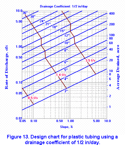
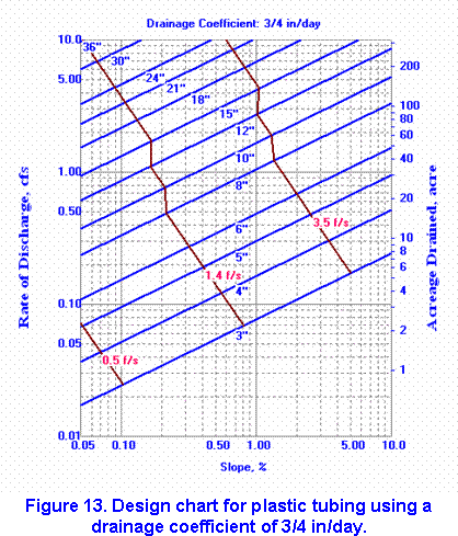
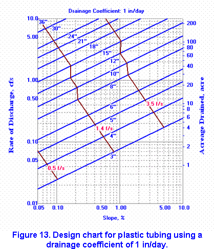
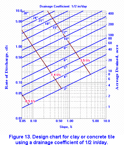
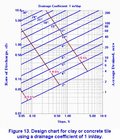
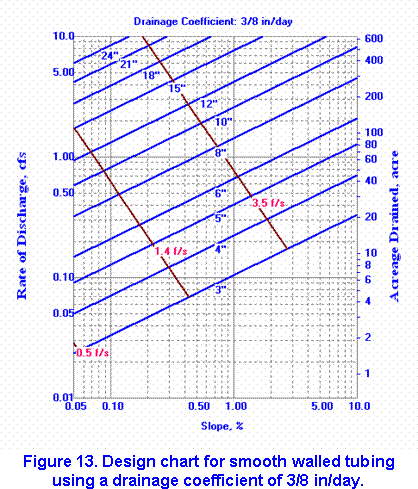
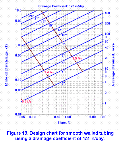
To determine the size of plastic drains or clay and concrete tile, refer to Figure 13 or the interactive Sizing Drainage Pipes program. First, find the appropriate drainage coefficient for the crop and drainage conditions. Next, locate the point at which a horizontal line through your acreage would intersect a vertical line through your drain grade or slope (horizontal axis). This point indicates the size of the drain and the velocity of water moving through it when it is flowing at capacity. The minimum cleaning velocity is 0.5 feet per second for drains not subject to the entry of fine sand or silt and 1.4 feet per second where fine sand or silt may enter. The rate of discharge information can be used in determining drain size at design slopes.
The smallest drain generally recommended for laterals is 4 inches. A drain 3 inches in diameter may be installed in locations where the grade is 0.2 percent or more, or where the design velocity exceeds 1.4 feet per second. The drain should be a minimum of 5 inches in diameter for a system with short laterals in sandy soils. Normally, 6 inches is the minimum diameter for drains located in organic soils and for main lines. For a subsurface system that contains tile lines exceeding 10 inches in diameter, it is preferable to use 2-foot or greater lengths to maintain alignment.
Drain length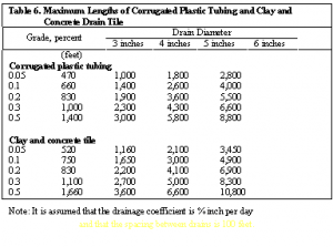
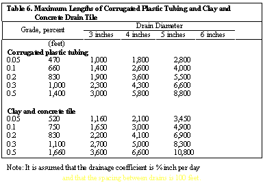
The length of lateral drains made of corrugated plastic drain tubing and concrete and clay drain tile should not exceed the values given in Table 6, assuming that the drains are spaced 100 feet apart and that the drainage coefficient is 3/8 inch. To determine drain length for other drainage coefficients and lateral spacings, multiply the length listed in Table 6 by the appropriate adjustment factor listed below for different coefficients and spacing.
Drain grade and velocity
When possible, subsurface drains should be placed at uniform depths. The range of grades on which they can be placed depends to some degree upon the topography of the land. The grade should be great enough to prevent silting but flat enough to prevent flow from exceeding the allowable velocity and subjecting the drain to excessive pressure. Too much flow would cause erosion around the drain. The grade should be as great as possible on flatlands. But you should not sacrifice adequate drain depth to increase the grade. The minimum grades of small drains are listed in Table 7 and can be evaluated with the Minimum Grade program .
Wherever the grades of drains are flatter than the minimum, take these precautions to reduce the amount of sediment.
- Make sure that the system has a free outlet so that backwater conditions will not further reduce velocity.
- Provide sediment traps and clean-out systems.
- Provide breathers and relief wells to vent the drain and to assure maximum flow.
- Protect the entire system from sedimentation by using filters and envelopes to prevent movement of the drain blinding materials.
For long laterals and main drains, the maximum velocity should be limited to those listed below, assuming that no protective measures are provided.
| Soil Texture | Velocity (feet/sec) |
| Sand and sandy loam | 3.5 |
| Silt and silt loam | 5.0 |
| Silty clay loam | 6.0 |
| Clay and clay loam | 7.0 |
| Coarse sand or gravel | 9.0 |
If protective measures do prove to be necessary, use one or more of the following.
For clay or concrete tile:
- Use tile uniform in size and shape with smooth ends.
- Lay the tile to secure a tight fit. The inside section of one tile should match that of the adjoining tile.
- Wrap open joints with tar- impregnated paper, burlap, or special filter material such as plastic sheets, fiberglass fabric, or properly graded sand and gravel.
- Select the least erodible soil for blinding.
- Tamp soil carefully under and alongside the tile before back- filling.
- Cement joints or use a drain with water-tight joints.
For corrugated plastic tubing or continuous pipe: Completely encase perforated drains with a filter material made of plastic, fiberglass, or a like material, or use a properly graded sand and gravel filter. Use non perforated corrugated plastic tubing or continuous pipe with taped or leak-proof connections.
Drain spacing and depth
The spacing and depth of drains influences the groundwater level between drains after a rain. Good drainage lowers the water table to at least 12 inches below the ground surface in the first 24 hours after a rain and to approximately 21 inches 48 hours after a rain. Incorrect spacing and depth could result in water remaining in the fields after 24 to 48 hours, significantly affecting crops (see Figure 14).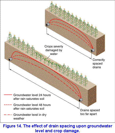
The spacing and depth required to keep the water table at the desired level are influenced by the permeability of the soil, depth to the barrier, the amount and frequency of rainfall, see page, capillary movement, and topography. Spacing and depth also influence each other. In general, you should increase the lateral spacing the deeper you place the drain. Spacing and depth recommendations are given in the Drainage Guidelines section for specific soils in Illinois . For soils not listed in the guidelines, keep in mind the following general principles about drain spacing and depth.
Drains in rapidly permeable soils should be spaced 200 to 300 feet apart, while those in moderately rapidly permeable soils should be spaced 100 to 200 feet apart. Where soil permeability is moderate, spacing should be 80 to 100 feet apart. In slowly permeable or moderately slowly permeable soils, drains should be spaced 30 to 70 feet apart or 60 to 80 feet apart, respectively.
With respect to general principles for depth, drains in moderate to moderately permeable mineral soils in humid areas should be installed at a depth of 3 to 5 feet. At this depth the drains will lower the water table to not less than 2 to 4 feet. Because the upward capillary action is limited in very sandy soils, the drains should be no deeper than 4 feet. In slowly permeable clay soils, the rate of lateral water movement does not increase with depth. Therefore, the drain is usually placed approximately 1 foot below the desired water table.
| General parallel drain lateral spacing and depths for different soils | |||||
| Soil Type |
Subsoil Permeability |
Drain Spacing (ft) for: | Drain Depth (ft) |
||
| Fair Drainage 1/4 in |
Good Drainage 3/8 in |
Excellent Drainage 1/2 in |
|||
| Clay loam | Very low | 70 | 50 | 35 | 3.0 – 3.5 |
| Silty clay loam | Low | 95 | 65 | 45 | 3.3 – 3.5 |
| Silt loam | Moderately low | 130 | 90 | 60 | 3.5 – 4.0 |
| Loam | Moderate | 200 | 140 | 95 | 3.8 – 4.3 |
| Sandy Loam | Moderately High | 300 | 210 | 150 | 4.0 – 4.5 |
The depth of drains also depends upon conditions other than those mentioned above – the depth of frost penetration, for example. If possible, place drains below the frost line to obtain optimum year-round drainage and to prevent damage to the line. Figure 15 shows the average annual depth of frost penetration for the state of Illinois.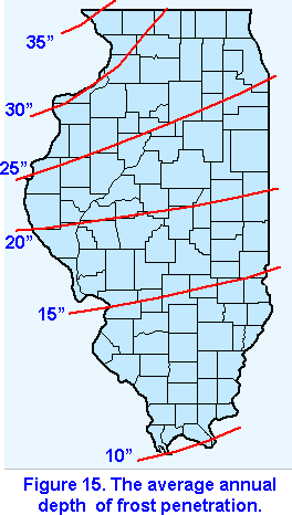
To protect a well-bedded sub-surface drain in a mineral soil from breakage or excess deflection of flexible tubing by heavy equipment, make sure that the drain has a minimum coverage of 2 feet. Where 3-inch drains are used both for drainage and sub-irrigation of shallow-rooted crops, the minimum depth may be 1.5 feet if heavy machinery is not used in the cropped area. The minimum depth of cover in organic soils should be 2.5 feet for normal field levels after initial subsidence. If controlled drainage is not provided to hold subsidence to a minimum, the depth of cover should be increased to 3 feet. The outlet should be deep enough for the lateral drain to have adequate grade and cover. When it is impossible to provide minimum cover for protection, use metal or some other continuous high-strength pipe.
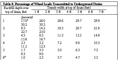
Live loads should be added to soil loads in the determination of depth. Table 8 shows the percentage of wheel loads transmitted to the drain. After determining load requirements, select the class of tile or tubing that will meet the requirements.
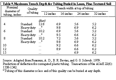
Plastic drain tubing should be installed in such a way that it does not deflect more than 20 percent of its inside diameter. The maximum trench depths for tubing that is buried in loose, fine-textured soils are listed in Table 9. Because the maximum depths listed in the table are based on a limited amount of research, they should be used with caution. Keep in mind, too, that these values are based on certain assumptions about corrugation design and pipe stiffness (which may not be the same for all commercial tubing) and about soil conditions. Because of variation in these characteristics, you may need to increase or decrease the maximum depths listed in Table 9.
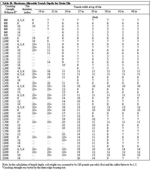
The maximum allowable trench depths for drain tile are listed in Table 10. To prevent overloading in deep and wide ditches, you may want to construct a subditch, either with a trenching machine or by hand, in the bottom of a wide ditch that has been excavated by a bulldozer, dragline, power shovel, or backhoe. It is now the width of the subditch measured at the top of the drain that influences the allowable load; the width of the excavation above that point is relatively not important. It is a good idea to backfill deep trenches in several stages to allow time for settlement between fillings.
Interceptor drains
An interceptor drain can be used in areas that are wet because of seepage from adjoining highlands. The drain is also used to intercept seepage or water that flows in a pervious layer on top of an impervious subsoil stratum.
Proper location of an interceptor drain is very important. An interceptor drain is usually buried at about the upstream boundary of the wet area. The drain is installed at approximate right angles to the flow of groundwater and intercepts a seep plane in the soil profile (Figure 16).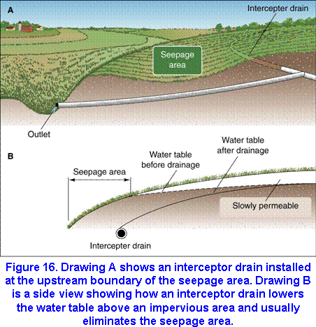 Adequate field investigations must be made to determine the amount of seepage and to identify seep planes. You can locate seep planes by making backhoe test pits or taking soil borings.
An interceptor drain must intercept the seep plane continuously, have adequate soil coverage, and be on a continuous grade toward the outlet. The drain is usually located one-half to one times its diameter deep in the impervious layer or seepage plane.
One or two properly spaced interceptor drains will usually dry up a wet area. The flow will often be continuous throughout much of the year. In a steeply graded depression or draw, the layout may consist of a main or submain located in the draw or to one side of it and interceptor lines located across the slope on grades slightly off contour.
To determine the size of an interceptor drain for a particular set of conditions, refer to the list below, which contains inflow rates for various soil textures. Measure or estimate the discharge of flowing springs and the direct entry of any surface flow through a surface inlet or filter. Add that figure to the rate of inflow. If the interceptor lines are being installed on sloping land, increase the inflow rate by 10 percent for slopes of 2 to 5 percent, by 20 percent for slopes of 5 to 12 percent, and by 30 percent for slopes of more than 12 percent. Once you have determined the inflow rate, you can then determine the drain size, using Figure 13 or theSizing Drainage Pipes program For interception areas where there is considerable seepage, the minimum drain size should be 6 inches.
| Soil Texture | Inflow rate per 1,000 feet of line (cu ft/sec) |
| Sandy loam | 0.07 to 0.25 |
| Silt loam | 0.04 to 0.10 |
| Clay and clay loam | 0.02 to 0.10 |
| Coarse sand or gravel | 0.15 to 1.00 |


Changing the direction of drains
You can change the horizontal direction of drain lines by several means. Curve the trench gradually on a radius of curvature that the trenching machine can dig while still maintaining grade. The joint spacings for tile should be no more than 1/16 to 1/8 inch. Use manufactured bends or fittings, or use junction boxes where drain lines make an abrupt change in direction or where two or more large drains join.
Special components
Outlet pipes
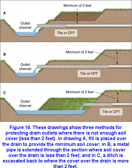
To protect drains from erosion and undermining, install outlet pipes on the end of all drains that outlet into an open ditch. Assuming that no surface water enters the ditch at the drain outlet, the most practical and economical protection is a length of continuous pipe that does not have perforations or open joints. The pipe should be long enough (a minimum of 8 feet) to ensure that no seepage will occur around the drain and cause erosion at the outlet. At least two-thirds of the pipe should be embedded in the bank to provide the required cantilever support. The flow line of the outlet pip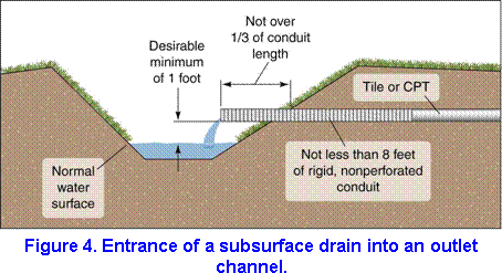 e should be at least 1 foot above the normal water surface in the outlet ditch (Figure 4). A pipe projecting into the ditch can either be damaged or destroyed by floating ice and debris or cause a serious ice jam. Where this possibility exists, the pipe should be recessed into the ditch bank (as shown in Figure 17) and protected with riprap. Where here is not enough soil cover at he outlet, use one of the methods shown in Figure 18 to protect he drain.
Where surface water does enter he ditch at the drain outlet, some type of structure should be installed to lower the surface flow safely to the ditch (Figure 19).
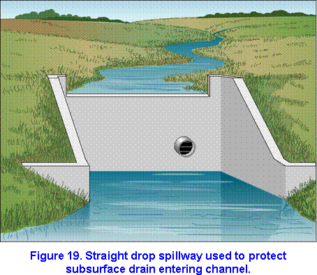
If there is no spoil bank, a straight-drop spillway is generally the best type of structure. But if there is a spoil bank and enough temporary storage for surface water, it is usually more economical to install a pipe drop-inlet. Sometimes you can move the drain outlet out of the waterway or divert the surface water to another location at least 60 to 75 feet away and lower the surface flow into the ditch over a sodded chute.
Animal guards
Animal guards such as rods, flap gates, and finger-type flap gates should be used on the outlets of all drains that are accessible to small animals (Figure 20). Fixed pins are suitable for lines that do not have surface-water inlets. Insert the pins horizontally through the end of the outlet pipe, not more than 11/2 inches apart. Check the outlet frequently to be sure that roots and other debris carried through the drain do not block the openings between pins.
Fixed pin guards are not suitable for lines that do have surface-water inlets because the guards can easily become plugged up by the small material that continually washes through them. For those lines, use flap gates made of noncorrosive material.
Drain crossings
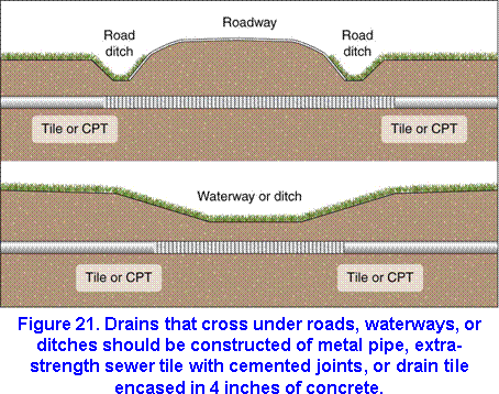
Where subsurface drains cross under waterways or other ditches, the conduits should be watertight and strong enough to withstand the loads put on them. Design conduits that pass under roadways to withstand the expected loads and meet the requirements of the appropriate railroad or highway authority (Figure 21). (Table 9 and Table 10 list the maximum allowable trench depths for tile and tubing, and Table 8 gives the percentages of wheel loads transmitted to underground drain.) Be sure to obtain written permission to construct drains under roads from the responsible road official. Protect shallow drains in depressional areas and near outlets against damage by farm and other equipment and by freezing and thawing.
Junction boxes and sediment traps
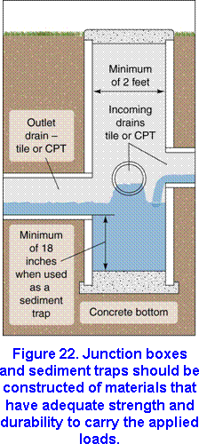
Junction boxes are used where two or more drains join at different elevations or where a drain changes direction abruptly. They can also serve as sediment traps, which are placed downstream from surface-water inlets to catch sediment and trash entering the line. Locate junction boxes in permanent fence rows or in noncultivated areas. Be sure that the capacity of the outlet drain equals the combined capacity of the incoming drain lines and that the elevation of the outlet drain’s flow line is at the same level or below the flow line of the lowest incoming drain (Figure 22). Place the junction box cover aboveground to provide easy access for inspection. In cultivated fields, the top of the box should be at least 18 inches below the ground surface.
Pressure relief wells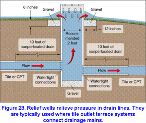
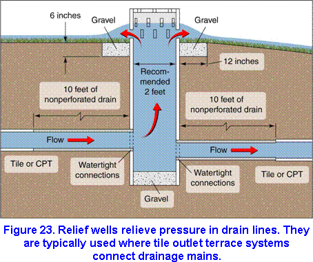
A well relieves pressure in drain lines that might otherwise cause them to blow out. A relief well can be constructed by placing a T connection in the line and fitting a riser vertically into the T (Figure 23).The riser should outlet at the ground surface; the exposed end should be covered with heavy wire mesh or grating. The size of the riser should be equal to or greater than the diameter of the line. Locate relief wells where the drain line might become overloaded for short periods. This is more apt to occur where there is a change from a steeper to a flatter grade and where there are surface inlets.
Pressure relief wells that are intended to function frequently (as with underground outlets that carry surface water from terraces or other temporary impoundments) should be designed to keep the hydraulic gradeline as low as possible, preferably below the ground line. This may best be achieved by outletting near the gradeline of a grassed waterway or surface drain.
Connections
Manufactured connections should be used for joining two tile lines at a junction. If connections are not available, the junction should be chipped, fitted, and sealed with cement mortar. For drainage systems constructed of corrugated plastic tubing, use manufactured fittings at all joints, at all changes in direction where the radius of the centerline is less than three times the diameter of the tubing, at changes in diameter, and at the end of the line. All connections must be compatible with the tubing. If certain fittings are not available, hand-cut holes are acceptable, provided that they are reinforced with cement mortar or other material that will make the joint tight. When making the connection, be careful not to create a means of obstructing flow or catching debris inside the conduit or allowing soil to enter the line.
Mains should be laid deep enough to permit the centerlines of the laterals to be joined at or above the centerline of the main.
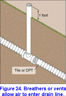
Breathers or vents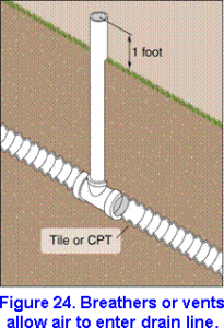
Breathers, sometimes referred to as vents, can be constructed as shown in Figure 24. They allow air to enter the drain for the purpose of venting the line. Breathers are usually installed where the line is longer than 1/4 mile or where the line changes from a flat to a steep grade and full flow occurs in the line with the flat grade.
Exposed material needs to have resistance to ultraviolet light and fire. The riser should be 4 inches in diameter for 15-inch and smaller drain lines and 6 inches for drain lines that are 18 inches or larger. Cover the top of the riser with a heavy wire-mesh screen or some type of perforated cap.
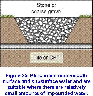
Blind inlets
Blind inlets remove both surface and subsurface water They are most useful in open fields because they do not hinder farming operations. Since blind inlets remove impounded water at a much lower rate than surface-water inlets, the former should not be used where there is a large amount of impounded water.
Described below is one method of constructing a blind inlet. Fill a section of the trench around and up to about 6 inches above the drain with stone, gravel, crushed rock, or a combination of these materials (see the section on envelopes, page 35). Grade the material upward from coarse to fine to within approximately 12 inches of the ground surface and cover the material with topsoil. To increase the intake of water, especially in areas where silting is a problem, use pea gravel, small stones, or coarse sand instead of topsoil (Figure 25).You can also construct the blind inlet of graded gravel. The length of time for which the blind inlet will be useful depends upon the care with which it is installed, the fill material, and the amount of sediment that reaches the inlet.
 .
. 
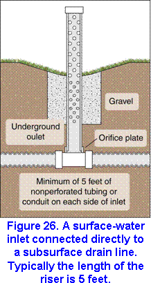
Surface-water inlets
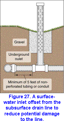
Surface-water inlets allow surface water to enter subsurface drains (Figure 26). Because of the high cost of carrying surface water in buried drains, inlets are recommended only for draining low areas where it is not feasible to install a surface drainage system. If you have to use surface-water inlets, place nonperforated tubing or conduit on each side of the riser. Since surface-water inlets may be a source of weakness in a drainage system, you might consider offsetting the inlet to one side of the line to reduce the hazard to the main line (Figure 27).
Surface-water inlets not projecting above the surface should be protected with a cone grate (often referred to as a “beehive”). The cone grate tends to float flood debris, preventing it from closing off the entrance.
Metal pipes and other durable materials with holes or slots may be used as inlets. Flow control devices may be necessary to limit the amount of water entering the drain. One way of limiting water flow is to install an orifice plate near the bottom of the inlet. Where it is likely that a substantial amount of sediment will enter the surface-water inlet, it is advisable to construct a sediment trap.
Filters and envelopes
The need for a filter or envelope depends upon the characteristics of the soil material at drain depth and the velocity of flow in the conduit. Filters may be required in sand, silt, and some organic soils to prevent sediment from accumulating in the drain. A filter is required where the base material is uniform, fine to medium sand and where flow reaches such high velocities that it moves the sand into the drain.
Filters may be sand and gravel envelopes or manufactured filter material. Most of the presently available, artificial, prefabricated filter materials, such as fiberglass, spun-bonded or knitted synthetic fabrics, and plastic filter cloth, act as protective filters. With time, however, these materials may partially clog and decrease flow into the drain. Manufactured filters should have openings of sufficient size and enough strength, durability, and permeability to provide constant filtering of the soil material and to protect the drain throughout the expected life of the system. Make sure that the manufacturer of the material has certified it for underground use. During installation the material should span all open joints and perforations without being stretched excessively. Be careful not to damage the material during installation. Any damaged areas should be replaced before backfilling.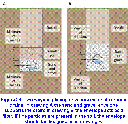
Installing envelope material around subsurface drains provides them proper bedding support and improves the flow of groundwater into the drain. Where it is not feasible to form a bedding groove for plastic drain tubing, envelope material can be substituted for bedding. The minimum thickness of the envelope may vary from 3 to 6 inches, depending on the type of equipment used to install the material and the availability of the gravel material. For all envelope designs, if the trench is wider than the specified width of the envelope, the trench must be filled on both sides with bedding material or a gravel envelope so that no space is left between the drain and the walls of the trench.
Figure 28 shows various ways of placing envelope materials around drains. Although gravel envelopes are not normally designed to be filters, they do act as partial filters because their gradation is better than that of the base material.
Preinstallation considerations
In order for a subsurface drainage system to perform properly, it must be installed correctly. Assuming that the system is well designed and constructed of high-quality materials, proper installation will greatly reduce maintenance and prolong the life of the system. Recommended installation techniques are provided for corrugated polyethylene tubing in ASTM installation standard F 449.
Plans and records
Ideally, all construction should follow a definite plan that has been prepared in advance by the designer of the system specifically for the drainage contractor. The plan should include profiles and construction notes for all mains and submains and a map showing the locations, sizes, and grades of all lines and other components of the system. The map also should show physical features so that components of the system can be readily located in the future for repairs and maintenance. The location of buried cables, pipelines, or other utilities also should be noted (long before construction begins, the owner should obtain any necessary permission or easements that might be required to cross the land of private owners, highways, railroads, etc.). In Illinois must utilies can be located by making a single call to JULIE.
The contractor should carefully examine the plan before work is begun and should not proceed with installation until the public utilities have marked the exact location of any buried obstacles at points where drains are to be constructed. As the work proceeds, the contractor should be careful to note on the plan and map any modifications in the design that are necessitated in the field, especially any changes in grade. Once the job is completed, the contractor should give the landowner the plan and map showing the system exactly as it was installed in the field. We recommend that the owner file one copy of the plan with the legal papers for the land and keep a working copy with the farm records. If a drainage system is designed in the field, the designer, with the help of the contractor, should prepare a final, as-constructed plan with notes for the landowner.
Inspection of materials
The contractor should inspect construction materials before and during installation. All materials should be satisfactory for the intended use and should meet the requirements described in the Materials section of this publication, and any additional requirements of the owner. Reject any defective or damaged clay or concrete drain tile; remove defective or damaged sections of plastic tubing. Make sure that the perforations in the plastic tubing are of the proper size.
Storage of materials
Drainage materials should be protected from damage during handling and storage. The storage area should be dry, well drained, and free of rodents, vegetation, and fire hazards. It should have a protected floor (peagravel or cement) and adequate security.
Take more precautions to protect plastic tubing. Where rodents could be a problem, we recommend that you use end caps. Tubing with filter wrap should either be stored inside or placed in protective bags. Since tubing can be harmed by excessive exposure to ultraviolet rays, protect it from sunlight when it is to be stored outside for a long period. To protect coils or reels of tubing from damage and deformation, lay them flat when they are stored for extended periods. Coils of tubing should be stacked no more than four high; reels should not be stacked.
Tree removal
Before installation begins, remember to remove willow, elm, soft maples, cottonwood, and other water-loving trees that grow within approximately 100 feet of the planned drainage lines. All other species of trees, with the possible exception of fruit trees, should be removed for a distance of 50 feet. If it is not possible to remove trees or to reroute the line, use a non perforated line with sealed joints throughout the root zone of the tree or trees.
Grade control
All drains should be installed at a predetermined grade that will give them the capacity required for the area to be drained. This grade should be maintained constantly during installation. The easiest way to control the grade is to use equipment that is designed especially for drainage installation. If you use a backhoe or other equipment, you must take extra precautions to ensure that the trench is shaped properly and the grade is maintained. Grade is normally maintained by the use of electronic, optical grade control devices (lasers).
Small and gradual variations from grade can be tolerated, providing the line still has adequate capacity after the variations. No reverse grade should be allowed.
If the trench is excavated below the designed grade, it should be filled to grade with gravel or well-pulverized soil and tamped enough to provide a firm foundation. The bottom of the trench should then be planed and shaped to grade.
Safety
Observe safety standards for persons and machines. Persons working in trenches should be protected from cave-ins, and they should not work alone. Moving parts of machinery should be protected by proper guards. Persons observing the work should not be permitted to come close to the excavating operation.
Trench method of installation
Constructing the trench
Construction of the trench should begin at the outlet and proceed upgrade. Align trenches in such a way that the drain can be laid in straight lines or in smooth curves. The width of the trench at the top of the drain should be the minimum required to permit installation and enable the bed to support the load on the drain. But there should be at least 3 inches of clearance on either side of the drain.
Tile should be bedded in an earth foundation that is shaped to fit the lower part of the tile. The foundation can be shaped in this way with most trenching machines. If you dig the trench with a backhoe, you will have to hand grade and shape the trench bottom to fit the tile.
For corrugated plastic tubing, a specially shaped groove must be made in the trench bottom if the design does not call for a gravel envelope. The groove provides side and bottom support to the lower part of the tubing and provides a means of controlling alignment during installation. The groove may be in the shape of a semicircle, trapezoid, or a 90-degree V. A 90-degree V groove of sufficient depth is recommended for 3- to 6-inch tubing. However, if the tubing is installed on a steep grade, shape the bottom of the trench to closely fit the tubing.
The groove for tubing can be formed or cut in a number of ways. With all methods, some type of a forming tool is attached to the shoe of the trenching machine. One method is to install a forming tool on the bottom of the shoe and use pressure to form the bedding groove. Another method is either to install a device on the front of the finishing shoe that will plow out the groove during the trenching operation or to attach special shaping cutters to the trenching wheel. The latter methods minimize soil compaction and do not reduce permeability as much as the first method.
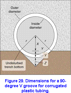 Figure 29 shows the dimensions of a 90-degree V groove. The depth at which 3- to 6-inch tubing is set in the groove will vary according to the size of the tubing. This depth can be evaluated with the V-Groove program. Keep this depth in mind when setting the gradeline. For tubing 8 inches or more in diameter, we recommend a curved bottom that more nearly fits the tubing rather than the 90-degree V groove.
If the drain is to be laid in a rock-cut, the trench should be overexcavated to a depth of 6 inches below grade level; this space should be filled with graded sand and gravel or well-pulverized soil and tamped enough to provide a firm foundation. Then, the bottom of the trench should be shaped and leveled to grade. The trench should be filled with designed bedding or envelope material to the top of the rock-cut.
Where the trench bottom is unstable, as in fine sandy soils or in soils containing quicksand, be extremely careful to keep sediment from entering the drain and to provide a firm foundation for the drain. When draining these types of soils, consider the following suggestions:
- Install the drain only when the soil profile is in the driest possible condition.
- Place stabilizing envelope materials under the drain.
- Cover the remainder of the drain with an envelope material.
- Use non perforated tubing, self-sealing sewer pipe, or continuous rigid pipe where there are small pockets of noncohesive soils less than 100 feet in length.
- If the drain is tile, be sure that the joints are snug. If tubing is used, take precautions to prevent it from floating.
If you find unstable soil at the trench bottom, you can remove and replace it with suitably graded foundation and bedding of processed stone or processed gravel, which will act as an impervious mat into which the unstable soil will not penetrate. The depth of the processed material depends on how unstable the soil is in the trench bottom. Install the foundation and bedding material in layers of no more than 6 inches, and compact. If the foundation contains large particles that create a hazard to the drain, provide a cushion of acceptable bedding material between the foundation and the drain.
Where stabilizer materials do not furnish adequate support, the drain should be placed in a 90-degree, rigid V, prefabricated foundation cradle in which the top of the V equals the outside diameter of the drain. Each section of the cradle must provide rigidity and continuous support throughout the entire length of the cradle. Occasionally, it is necessary to place the cradle on piling; drive pairs of posts along the edge of the cradle into solid material to provide the required support.
If the soil in the trench wall is unstable, the trench sidewalls may cave in and cause tubing failure. This problem may arise where excavation is below groundwater level or in saturated sand. Unstable trench walls may also cause misalignment of tile lines. Where there are unstable trench sidewalls, you should protect the tubing or tile by some means until the drain has been properly laid and blinded. In some cases, the trencher shield behind the shoe can be made longer to protect a greater length of the trench during construction. To install drains in unstable soils, use a fast-moving trencher or trench less drain plow that can maintain continuous forward motion while disturbing the soil as little as possible.
Installing the drains
Listed below are some guidelines to follow when installing drains:
- Remove all soil or debris inside drains before installation.
- Make sure the drain is free from clinging wet or frozen material that could hinder laying the drain on grade.
- Begin laying tile or tubing at the outlet and progress upgrade. If possible, place the drain inside the shoe casing of the trencherduring the trenching operation.
- Automatic drain-laying devices are acceptable, provided that they can lay the drain according to the requirements stated in this publication.
- Lay tubing in the groove and tile on a firm bed that is free of loose soil on the planned grade
- Hold plastic tubing in position on grade immediately after installation by careful placement of blinding material.
- Where lengths of plastic tubing are to be joined, cut the ends square and remove all ragged or burred edges.
- Use a plastic coupling to secure the ends of the tubing in proper alignment and to prevent the joint from separating during installation.
- Before work is suspended for the day, blind and backfill all drains laid in trenches.
- Close any open ends tightly with an end plug.
- Use continuous pipe within 100 feet of trees.
Any stretch that occurs during installation of tubing will decrease its strength somewhat and may pull perforations open wider than is desirable. The amount of stretch that occurs during installation depends on the temperature of the tubing at the time it is installed, the amount and duration of drag that occurs when the tubing is fed through the installation equipment, and the stretch resistance of the tubing. Tubing should not be stretched so much that its stiffness is reduced to less than the minimum allowable pipe stiffness. Stretch, which is expressed as a percentage increase of length, should not exceed 5 percent. The use of a power feeder is recommended for all sizes of tubing.
The internal wall temperature of plastic tubing can reach 1500 F. or more when it is strung out in a field on a hot, bright day. The ability of corrugated polyethylene tubing to resist deflection is reduced by about 40 percent when its temperature rises from 700 to 1000 F. and by about 50 percent when it increases from 700 to 1200 F. Therefore, it is essential that the contractor take precautions in hot weather to keep sharp heavy objects from striking the tubing and to prevent excessive pull on the tubing during installation. The tubing will regain its strength when its temperature returns to that of the surrounding soil, which usually occurs five minutes or less after installation.
The stiffness of tubing increases and its flexibility decreases as its temperature is lowered. Rapidly uncoiling tubing in cold weather stresses it excessively and may cause it to crack. The tubing may also have a tendency to coil in cold weather; it is then difficult to lay flat and must be handled with extra care. Ask the manufacturer for recommendations on handling the material in hot or cold weather.
When plastic tubing floats in water during installation, it is difficult to get blinding material around and over the tubing without getting the material underneath it and causing misalignment. You can prevent floating by holding the tubing in place until blinding is completed.
Blinding
Blinding is the placement of bedding material consisting of loose, mellow soil on the sides and over the top of the drain to a depth of 6 inches. The bedding material must permit water to reach the drain easily. Except in areas where chemical deposits in and around the drain area are a problem, the bedding material should be friable top soil or other porous soil. Fine sand should not be placed directly on or around the drain. In soils with low permeability where blinding with soil is not adequate, a suitable envelope should be used. Blinding is not necessary where drains are placed in sand and gravel filters or envelopes.
A number of blinding methods have proven to be acceptable. Some contractors consider blinding so important that they place the material by hand around and over the drain. There are a number of mechanical blinding devices that can be mounted on the trencher. These devices take material from near the top of the trench and place it around and over the drain. Their main advantages are that they blind the drain immediately after laying it, use the most suitable blinding material that is readily available, and reduce labor requirements.
All drains should be blinded immediately to maintain alignment and to protect them from falling rocks, ditch cave-ins, and backfill operations.Blinding immediately also will help maintain proper alignment of tubing in the groove and protect it when the remaining excavated material is placed in the trench. Careful soil placement on both sides of the tubing is necessary to provide good side support, which will reduce deflection of the tubing. Hold tubing in place in the trench until it is secured by blinding. This step is especially important when water is in the trench and when the air temperature is below 45 F Under those conditions, you may want to increase the quantity of blinding material.
No stones or other hard objects should be allowed to come into contact with the drain. These objects apply point loads and may cause the drain to fail. Blinding provides protection for the drain during the backfilling operation when the impact of rocks and hard clods could damage it. All lines should be carefully inspected for grade alignment and other specifications before backfilling.
Backfilling
At the conclusion of each day’s work, the end of the drain line should be stoppered and the trench backfilled to prevent sediment or debris from entering the line in case of rain. Backfilling should be done even sooner if there is a chance of heavy rain or freezing temperatures. The upper end of each drain should be tightly covered with a manufactured plug or equivalent material.
Various methods can be used to move the remaining excavated material back into the trench and mound it up and over the trench to allow for settlement. These include graders, bulldozers, and auger and conveyer methods. The backfill material should be placed in the trench in such a manner that displacement of the drain will not occur. It is preferable to place the material on an angle so that it flows down the front slope. Avoid large stones, clods, and heavy direct loads during backfill operations. If you are installing tubing on a hot day and the tubing feels warm to the touch (1000 F.), delay the backfilling until the tubing reaches the soil temperature.
Trenchless method of installation
In the trench less plow method, tubing is placed at a prescribed depth in an open channel beneath a temporarily displaced wedge or column of soil. The trench less plow constructs a smooth-bottomed opening in the soil, maintains the opening until the tubing has been properly installed, and then surrounds it with permeable material.
The plow blade is designed to lift and split the overburden as it moves forward. The lifting action causes a deformation and disruption of the soil upward and outward at an angle on both sides of the plow blade. The slot should be fissured and loosened rather than compacted. The size of the shoe and drain-placing attachment should conform to the outside diameter of the tubing.
Critical depth
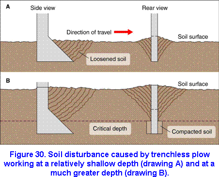 The way the trench less plow moves through the soil influences whether the slot wall is fissured or compacted. A plow 3 to 5 inches wide working at a relatively shallow depth of 3 feet or less in dry soil will disturb the soil as shown in Figure 30a. The soil is broken loose from the base of the plow, heaves forward and upward ahead of the tine, and falls back around the tubing as the plow moves on. This type of disturbance creates cracks and fissures without causing compaction. The same plow working at a much greater depth of 6 to 7 feet in dry soil may tend to move the soil as shown in Figure 30b. Near the surface the soil is disturbed much as it is in drawing A. But below a certain depth, the plow may compress the soil sideways, causing it to become compacted and reducing its permeability. Between these two extremes of working depth there is a certain depth, termed critical depth, where the transition between one type of soil disturbance and the other occurs. This critical depth is the maximum depth at which the trench less plow can work without causing compaction around the tubing. The critical depth depends upon the forward inclination of the tine, the tine width, the soil moisture content, and the soil density.
In a uniformly compact, dry seed bed, the critical depth will be approximately 15 times the tine width. As the surface layers become very dry and strong or if the soil is of low bulk density and contains large air-filled pores, the critical depth will be reduced to about 10 times the tine width. You can sometimes lower the critical depth by loosening the surface layers of the soil to a depth of 8 to 16 inches in a strip approximately one and one-half times the working depth of the plow. The shallow tining can be done as the plow “returns empty” before the next run. An alternative is to use a double-pass system. The first pass with the plow is made at approximately two-thirds the final depth. Where the critical depth is above the working depth, using a wider tine and loosening the soil surface will reduce the draft force, often by a substantial amount.
Soil condition
Because soil texture and moisture vary considerably, the soil disruption patterns caused by the trench less plow will vary. The zone of disturbed soil extends upward and outward at various angles from the vertical, depending on soil conditions, depth, and plow geometry. Soils ranging from sands to clay-loam have properties that permit them to be fractured very readily by the plow. In fact, when the surface layer of these soils is loose, it tends to flow down behind the tubing just as it would during a blinding operation. Wet soil that has high clay content is more likely than other soil types to develop soil structure and compaction problems. Both radial and surface compaction can occur where tubing is installed in heavy clay soils or wet soil. High-clay soils that are dry, however, can be fractured and fissured to a high degree, facilitating movement of water to the tubing.
Plows do not appear to be affected as much by rocks as are trenchers. In areas where rocks are a problem, the operator should flag any rocks he comes across so that they can later be inspected and removed if necessary. A plow will tend to push smaller rocks aside and move around the larger ones. When large rocks are encountered above or near grade, the plow tends to bounce over them, disrupting the tubing grade. If a rock deflects the plow upward a small distance, an alert operator will, where the slope permits, make a small adjustment in grade from that point on to avoid leaving a hump in the line that would have to be corrected later. If there is an adverse deviation in grade, the point of deviation should be marked. The tubing should be excavated at that point and the grade corrected. The grade should be controlled automatically by means of a laser.
Blinding
To keep the tubing on grade, trench less plows should be fitted with a device that brings blinding soil over the tubing as it is placed. Where the surface layer is loose, it will flow down freely behind the tubing boot and cover the top of the tubing. This cover is desirable as long as the surface material is highly permeable and stable, but siltation could occur if the surface material is very fine. If a filter is used, a covering of medium to coarse sand around the tubing could enhance inflow.
Stringing tubing
Because trench less plows operate at high speed, it is sometimes difficult to keep pace when stringing the tubing in the field by hand before installation. To meet the requirements of high-speed plows and to reduce labor and materials costs, spools mounted on trailers have been developed.
Stretch
The amount of stretch depends on the stretch resistance of the tubing, the amount and duration of drag on the tubing as it is fed through the machine, and the temperature of the tubing at the time it is installed. Stretch may also be influenced by your method of handling the tubing when you string it in the field and the way the tubing is picked up and fed into the installation chute. Tubing should not be stretched so much that its stiffness is reduced to less than the minimum allowable pipe stiffness. During installation, stretch should not exceed 5 percent. We recommend that trench less plows be equipped with a power feeder to reduce stretch.
Maintenance
Although subsurface drainage systems do not require extensive maintenance, the maintenance that is required is extremely important. If the subsurface drains are working, water will stand in the field for only a short time after a heavy rain. If water stands for a few days, the drain may be partly or completely blocked. With drainage systems that have inspection wells or sediment traps, be sure to check the amount and rate of flow at these structures and at the outlets after a heavy rain. A change in flow may indicate that there is a blockage somewhere in the line. Regular inspection of the drainage system is essential. Prompt repair of any drain failure will keep the system in good working order and prevent permanent damage to it.
Outlet ditches
Many subsurface drainage systems fail because the outlet ditches are blocked. If the outlet ditch is filled with sediment, a survey should be conducted to determine how much cleanout work will be required. You should also find out whether some type of conservation practice could be used on the contributing watershed to reduce soil movement.
Surface inlets
Poorly constructed surface inlets are subject to severe damage and require frequent repair Because inlet covers often become sealed with trash, they should be checked frequently. Clean the covers after a heavy rain and replace them carefully. If a cover is removed, trash can enter and block the line.
Blowouts
Repair holes over subsurface drains at once. Otherwise, large amounts of soil may wash into the lines and block the entire system. Holes form where a drain is broken or where joints or slots are too wide. If the tile is broken, replace it. If the joint is too wide, place tile bats (pieces of broken tile) over the joint to prevent soil from washing into the line. To repair crushed or punctured corrugated plastic tubing, cut the damaged segment from the line and replace it with new tubing, using the manufacturer’s couplers.
Sediment
Sediment traps can be used for subsurface drains that are laid in fine sand or silty soils. If the traps are cleaned periodically, they will keep soil from filling the lines. Clean the traps every few days just after the lines are laid because at first sizeable quantities of fine soil will wash in through the joints between tiles or through perforations in plastic tubing. After one freezing and thawing cycle, soil will wash in more slowly, and you will need to check the traps only once or twice a year. You can gain access to drainage lines and flush them through inspection wells.
Tree roots
Willow , elm, soft maple, cottonwood, and other water-loving trees that grow within approximately 100 feet of the drain should be removed. Maintain a clearance of 50 feet between the drain and other species of trees.
Ochre accumulations
Ochre, which is an iron oxide, may block the drain when iron in solution moves from the soil to the drain and accumulates there. The process by which ochre accumulates may be chemical, microbial, or both. Ochre usually enters drains through organic soils but has been known to occur in other soils as well. There is no foolproof solution (except construction of open ditches) to the ochre problem. Jetting the drain with an acid solution has proven successful in some areas, but that remedy is very costly.
Pumping plants
Where it is impossible or uneconomical to install outlets for drainage, drainage pumping plants can be used to remove excess surface water or groundwater. Pumping plants are also used where outlets are adequate except during prolonged periods of high water. If you are considering installing a pumping plant, be sure that its use is within the limitations of Illinois drainage law.
In solving drainage problems that involve pumping, take into account the capacity of the drainage system outlet, the capacity of the pump, its location and type, and the size of the sump. Determine the cost of all practical solutions. To be economically feasible, a pumping plant must be designed in such a way that annual operation costs are low. A pump that costs relatively little to install but that has a high annual cost of operation may not be the most economical.
A preliminary survey will determine the condition of the drainage outlet and help you decide whether pumping is required. A drainage system with a pumping plant that is designed into the system will usually function much more efficiently than one to which the pump is added later when the outlet is found to be inadequate.
The pumping plant must be designed to pump enough water to provide adequate drainage against the total head expected. (Total head considers all possible sources of resistance, from elevation to friction to couplings and joints.) Because pumping plants that are designed to pump surface runoff are complex and expensive, as much surface runoff as possible should be diverted from the site of the plant.
Selecting a site
The pumping plant should be located where it can best serve its purpose. In choosing a location, consider the stability of the foundation material, accessibility for servicing, proximity to sources of power, and susceptibility to vandalism. In areas where ample sump storage is available, the pumping plant should be located so as to take maximum advantage of the storage. Select a location that will permit safe discharge into the outlet with a minimum of construction outside the diked area. If possible, locate the plant in a place that is readily accessible in all types of weather.
The requirement of a stable foundation is an important aspect in selecting a location. Before deciding upon a site, make borings to ensure that the location has the best foundation and that it meets as many of the other site requirements as possible.
Selecting pumps
In selecting a pump, consider the type, characteristics, capacity, total head, the kind and source of power, shape and size of pump, housing, and method of operation. Pumps used for pump drainage are in the high-volume, low-head class. This class includes axial-flow propeller pumps and certain centrifugal pumps. For pumping from small capacity tile, you can use commercial sump pumps. Determine pumping volumes and heads carefully since friction factors become critical at settings other than those recommended by the manufacturer.
Electric power permits automatic operation and eliminates the need for daily fueling or servicing. Usually, a 10-horsepower motor is the largest that can be used on single-phase, 230-volt lines. Larger motors can be operated on three-phase power, which is available in some areas, or where phase converters can be used on single-phase power lines. If you plan to use electric power for pump drainage installations, consult the power supplier for suggestions and recommendations as to the best arrangement. If electric power is not available, you can operate the pump with diesel, gasoline, or LP gas stationary power units. Belt or power takeoff drives can be used to couple farm tractors to the pump. The size of the pump depends upon the total head and the quantity of water pumped. The rated size is usually designated by the diameter of the pipe column at the discharge end of the pump. The design column velocity in the discharge pipe may range from 7 to 12 feet per second, with the highest efficiency usually occurring at values of 8 to 10 feet per second.
Pump capacity
The required capacity of pumping plants can be determined from drainage coefficients applied to the area served, empirical formulas, a study of existing installations, or direct analysis using hydrologic procedures. The capacity of pumping plants for drainage areas of up to 1 square mile can be determined from applicable drainage coefficients (Table 5) or computed through hydrologic procedures. Hydrologic procedures should always be used whenever the drainage area exceeds 1 square mile. If you determine pump capacity from the drainage coefficient, use the following equation:
Q = 18.9 x C x A
where
Q = pump capacity, gallons per minute (GPM),
C = drainage coefficient (inches per 24 hours),
A = area of the watershed (acres).
Regardless of the method you use, be sure that the pump capacity is no less than the minimum values suggested below. Where only subsurface drainage water is pumped, the capacity of the pump should be no less than the maximum capacity of the drainage system plus 20 percent. When both subsurface and surface water are to be pumped for field crops, the pump should have the capacity to remove 1 inch of water from the contributing drainage area in 24 hours. When special or high-value crops are to be grown, the pump should be able to remove 1.5 to 4 inches of water in 24 hours, depending upon how much runoff water can be stored in the ditches and watershed and upon the degree of protection desired. Where seepage is a problem, select a pump with additional capacity.
Power requirements
The power required to achieve the designed pumping rate depends upon the head against which the water must be pumped and the efficiency of the plant. The horsepower required to move a given quantity of water against a specific head can be calculated with this formula:
![]()
where
HP = horsepower required to move the water,
Q = pump capacity (GPM),
H = total head (feet), which includes the difference in elevation between inlet water level and discharge water level as well as friction losses in the pump and fittings
e = efficiency of the unit (equal to the pump efficiency times the drive efficiency; pump efficiency varies from 50 to 75 percent and drive efficiency from 90 to 100 percent).
The horsepower you determine with this formula will be the continuous-duty requirement. For electric motors, this figure will be the nameplate rating. For
internal combustion engines, the minimum engine size will be the calculated horsepower plus the power required to operate accessories.
Before installing the pumping system, estimate the daily cost of pumping to complete a cost-benefit ratio. If the source of power is an electric motor, you can use this information in making the computations:
1 horsepower/day = 17.9 kilowatt hrs/day
Water storage
To prevent the motor from starting too frequently, you must provide space for temporary storage of water. In small areas an enclosed sump or pump bay may be enough storage. Enclosed sumps can be constructed from silo staves, manhole blocks, or a series of large sewer or metal pipe sections. For large subsurface drainage systems where subsurface water must be pumped, an open ditch or large pit is usually the best type of storage.For automatic operation, provide enough water storage so that the maximum number of operation cycles will be limited to 10 per hour. Estimate the required storage using these formulas:

where
Q = pump capacity (GPM)
d = the depth (in feet) of storage or distance between water levels that will start and stop pump operations,
N = cycles per hour.
The amount of active water storage must be greater for manually operated pumps than for automatic ones. The amount also depends upon the number of times the operator is willing to start the pump. Where the number of starts is limited to two a day, estimate the active storage desirable using these formulas:
where
Q = pump capacity (GPM)
d = the depth (in feet) of storage or distance between water levels that will start and stop pump operations,
N = cycles per hour.
The depth of storage (or distance between the water level at which the pump starts and at which it stops) should be about 2 feet for sumps and 1 foot for ditches. This depth reduces changes in the operating characteristics of the pump caused by changes in water level. Sumps should have a paved base and weep holes in the walls. The base provides a solid foundation for the sump wall and supports the weight of the pump and sump cover. Weep holes prevent flotation of the sump.
Pump bay
The sump or bay should be designed after the pump has been selected. Be sure to provide proper clearance and submergence in the pump bay for the pump you select (most manufacturers make recommendations for these dimensions), and protect the pump and motor from flooding at all times. See Figure 31.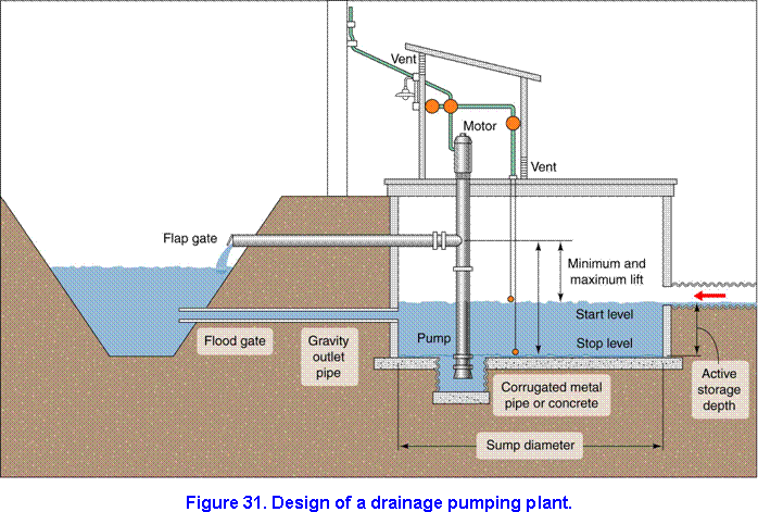
Operation and cycling
Although pumping is cyclic in design, the electric motor used to power a pump should have a continuous load rating to take care of sustained water inflow. Electric motors can easily be controlled by float switches. An internal combustion engine will have to be controlled manually for certain periods, or it can be made automatic by some kind of throttle or clutch control. Automatic safety cutouts will eliminate the need for an operator during most of the time the engine is running. Safety cutouts (based on engine temperature, engine oil pressure, or pump pressure) should be attached to any engine that is to be left running unattended for any length of time.
Trash racks
Provide trash racks or protective screening to prevent floating debris from entering the sump and damaging the pump. The velocity of flow through the rack should not exceed 2 feet per second. Recommended spacing for trash rack bars is 3/4 inch for a pump 16 inches in diameter, 1 to 1.5 inches for diameters 18 to 24 inches, and 2 inches for ones 30 to 42 inches.
The trash rack should be shaped so that it can easily be cleaned by hand, or it should be equipped with mechanical cleaners. If the pump is too small for trash racks, use galvanized basket strainers to prevent small gravel and debris from entering the sump. For more details on the design of pumping plants, refer to Chapter 7, “Drainage of Agricultural Land” in Section 16 of the Natural Resources Conservation Service National Engineering Handbook.’