Introduction
Most farm plans for soil and water conservation must, to be effective, include grassed waterways as part of their design. The wide, shallow, sod-lined channels of these waterways safely dispose of surface water from heavy rains and prevent the formation of gullies. Wherever surface runoff water from more than a few acres collects, a gully often forms. A grassed waterway is needed to prevent the resulting erosion.
Grassed waterways can make farming more convenient. If designed and constructed properly, they can be crossed easily with farm equipment. Possible damage to equipment taken across a gully can thus be avoided.
Land used for waterways is not wasted. The success of the total soil and water conservation program on the farm depends on the proper removal of surface runoff water through these waterways. The area needed for waterways should therefore be used for its intended purpose. The production of forage or the use of the land as a wildlife habitat should be secondary to the continued, proper functioning of the waterway as a means of carrying runoff and preventing erosion.
When making a decision to build a grassed waterway, the landowner should first compute the cost and then select the best time of year for construction. In Illinois the best time is usually midsummer: small grains can be grown earlier, and the waterway constructed after the grain is harvested. Grasses can be seeded right after construction.
Applicability
A grassed waterway is intended to convey water without eroding the soil. It is therefore important that an overland flow regime be maintained and that the water be prevented from becoming channelized. Even small irregularities in the soil surface will disrupt the smooth, even flow of water down the waterway, directing the water into a small, concentrated channel. The flow velocity will then become very high in this small channel and lead to erosion.
Grassed waterways are used for the following purposes:
- to drain terraces or diversions
- to dispose of water in road ditches
- to stabilize a natural draw that is eroding
- to stabilize a natural draw to which additional runoff water is being added by contours or terraces
It is not considered a desirable conservation practice to modify an conservation practice to modify an existing natural watercourse if it is currently carrying water and if the channel is not eroding. Such a draw might contain a meandering, noneroding channel vegetated with brush and trees that, in addition to holding the soil in place, provide a valuable habitat for quails, rabbits, pheasants, meadowlarks, cardinals, and other desirable wildlife.
Requirements
To allow construction of a grassed waterway, an area must have enough soil to establish and maintain a stand of grass. A stable outlet is also essential. If a stable natural outlet is not available, then a structure is necessary. In addition, tile drainage may be required beneath the waterway.
Assistance
The county Extension adviser can give advice on the general applicability of the practice to a particular farm situation. The county soil and water conservation district can then be contacted about a specific conservation plan. The district conservationist of the Soil Conservation Service can provide technical assistance for developing and implementing a conservation plan that incorporates the waterways into a total resource management system. Information about cost- share assistance can be obtained from the county office of the Agricultural Stabilization and Conservation Service.
Sequence of Construction
A grassed waterway should be built as a part of a total conservation program. If land treatment measures are needed to control soil losses on the land draining into the grassed waterway, then these measures should be completed before the waterway is built. Otherwise the waterway will be damaged and may require excessive maintenance and reconstruction.
If terraces are to be built to control upland erosion, then the grassed waterway may be used as an outlet for the water collected by the terrace system. In this case the grassed waterway should be built first so that when the terraces are built, the outlet will already be available.
Hydrologic design
Rainfall
The waterway should be sized to carry the runoff resulting from the maximum 24-hour rainfall expected in a 10-year return period. This rainfall can be read from the map in Figure 1 . It varies from 4 inches in northeast Illinois to 5 inches at the southern tip of Illinois.
Hydrologic Soil Group
To determine runoff volume, one must know the hydrologic soil group that is dominant on the watershed to be drained by the waterway. Table 1 lists Illinois soils and their hydrologic soil groups, namely A, B, C or D. There are usually several soils on each watershed. The most representative category from A, B, C, or D should be selected.
Curve Number
The runoff from a soil also depends on the land use, and runoff curve numbers (RCN) provide and index of this runoff. Table 2 gives curve numbers of the hydrologic soil groups A, B, C, and D with various land uses.
Watershed Slope
The watershed should be judged as being flat, moderate, or steep in slope by reference to the following key:
Slope(%) Description
0 to 2 ………….Flat
3 to 7 ………….Moderate
Over 7 ………..Steep
The slope is that of the total land area contributing runoff to the waterway. This slope is not the channel grade.
Peak Flow
The graphs in Figures 2, 3, and 4 show the peak flow in cubic feet per second (cfs) to be expected from watersheds of 5 to 200 acres, for rainfalls from 4 to 5 inches, and for curve numbers from 60 to 90. Figure 2 pertains to watersheds with a flat slope; Figure 3 to watersheds with a moderate slope; and Figure 4 to watersheds with a steep slope. By reading the appropriate graph, one can determine the peak flow. This is the flow rate (cfs) that the grassed waterway must be designed to carry.
Shape and dimension
General Layout
A natural drainageway should be used if possible. Other desirable features are an existing stable outlet for the drainageway; soil and moisture conditions already favorable for growing grass; and enough depth in the drainageway to allow for outlets from terraces, diversions, or crop rows at the grade of the constructed waterway without necessitating structures.
Drainage Area
Walk the boundary of the watershed and sketch it on a map or aerial photo, then measure the area. The size of the waterway depends on the peak flow, which in turn is proportional to the drainage area. Be sure to include the drainage area. Be sure to include the drainage area that may lie across the fence and belong to another landowner.
A field survey should be made along the course of the proposed waterway. Make a profile of the existing natural channel including cross sections. The waterway should then be divided into reaches having an approximately uniform slope and cross section. This will allow the waterway to be constructed in such a way that a minimum amount of earth will be moved. A significant break in slope makes a point of division between reaches. The entrance point of tributary – where the watershed is significantly increased – is also a natural point of division between reaches. By using the drainage area for each reach and calculating the peak flow, one can design the waterway according to the reaches. During construction, the slope and shape of each reach is gradually adjusted to that of the next reach.
Shape
The cross-sectional shape of the waterway should be parabolic – a shape in nature generally found to be suitable for a stable channel and one in which small flows are least likely to meander. The shape allows easy crossing with farm equipment if the side slopes at the edge of the channel are gentler than 5 to 1, as indicated in Table 3. Shown in Figure 5 is a sketch of the parabolic shape. T is the top width in feet and d is the maximum depth in feet occurring at the centerline. The shape is easy to visualize and build because at a width of 0.5 T the depth is 0.75 d, and at a width of 0.7 T the depth is 0.5 d.
Flow Velocity
Because the erosion resistance of soil increases with dense vegetation, the maximum allowable flow velocity in feet per second (fps) is related to the thickness or density of the grass that covers the channel bed. Table 4 shows allowable velocities. In determining the width and depth of the channel required to carry the peak flow, it is necessary, as will be shown, to manipulate the velocity and flow area so that the channel will be large enough, stable, and crossable with farm implements.
Capacity
Different grasses vary in their resistance to the flow of water. The stems and leaves of the grass bend and oscillate under the influence of the velocity and the depth of flow. This flow can be predicted by the Manning equation, which is given and explained later in this publication.
Flow resistance is expressed in the Manning equation as the roughness coefficient or n value. Research published by the Soil Conservation Service (1954) relates the n value in the Manning equation to the product, VR; that is, the velocity, V, multiplied by the hydraulic radius, R. These factors are related by a family of curves having different values of retardance. The curves are shown in Figure 6. The retardance categories of A, B, C, D, and E are expressed for various grasses and grass management conditions.
Waterway Design
Table 5 is presented here as a design table applicable to all general conditions in Illinois. Its use allows the selection of a top width, T, and a depth, d, for a parabolic channel that will carry the flow required. Table 5 gives values of T and d that have been calculated using the Manning equation with two selected values of retardance, B and D, as described below.
For the purpose of checking the stability of the channel, a retardance class of D has been used to calculate the maximum velocity normally expected to occur in that channel. The extreme left column of Table 5 gives values for the rate of flow, Q, in cubic feet per second. The top width, T, and the depth, d, are given for each value of channel slope, S, of a parabolic channel that will carry the flow, Q, given in the left column. At the top of each column is the value of V1, which is the maximum allowable velocity of 4 feet per second under normal conditions. Retardance D is considered appropriate for almost all grass mixtures recommended for use in Illinois when the waterway is mowed regularly and the grass is generally less than 6 inches high.
An additional calculation has been made for each entry in Table 5 so that the capacity of the channel can be checked. The recommended grass mixtures have a much higher resistance to flow when the grass is unmowed. Grass may then be 12 to 18 inches high, at which time retardance B is appropriate for use. For each flow rate in Table 5, a value of V2 is shown, which is always smaller than V1. The value of V2 is the average flow velocity in the given channel as calculated by the Manning equation using retardance B. The channel must be, and is, able to carry the flow when the lower velocity, V2, occurs. (See Table 6.)
Subsurface Drainage
A drainageway that is normally wet should be tiled before a good grassed waterway can be established.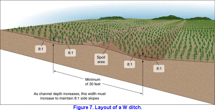
The design of the waterway should therefore include the tile drainage. As shown in Figure 7, the tile line should be at least 2 feet lower than the center of the constructed waterway and at least one-third the width of the waterway as measured from the center-line of the waterway. Tiling provides adequate drainage and also reduces erosion f the back fill materials in the tile drain. The size of the tile must be such that the tilling not only drains the waterway channel effectively, but also fits into the entire local tile drainage system. Such a tile line, located adjacent to a waterway, often acts as a tile main, serving other upstream tile lines.
Construction
Methods
Remove all brush and rocks larger than 6 inches in diameter and bury them elsewhere, not beneath the waterway.
Drive centerline stakes to mark the intended waterway. Using offset stakes will help maintain planned grades and aid in checking construction. If the subsoil in this region will not support the growth of grass, remove the topsoil from the waterway and stockpile it nearby, out of the way.
Shape the waterway to the design grade and parabloic cross section. Fill the gullies gradually. Pack the fill to prevent settling in the future. Be conscious of safety when operating the equipment. Do not drive too near the edge of a steep gully. Spread the stockpiled topsoil evenly over the surface of the shaped waterway.
Frequently measure the width, depth, and grade of the waterway to be sure it complies with the design. These conditions are important:
- Centerline elevations must be as planned so that a uniform grade is maintained.
- Depth at a distance of one-fourthfothe top width from the center should change from d to 0.75d. (See Figure 5.)
- Edges should be feathered into the adjacent topography outside the design cross section. The final shaping of the waterway surface is critical. The surface must be smooth because small mounds or holes will create local flow velocities that will destroy the waterway by erosion. All changes in grade from one reach to the next should be smooth and gentle.
If a waterway is improperly constructed so that it has a nonuniform grade or an incorrect cross-sectional shape, it is likely to be unstable and to erode rapidly.
Establishment of grass
Importance
Probably the single most important condition in establishing a grassed waterway is that the grass be planted immediately after earthmoving is completed. If the grass is not established quickly, the bare earth of the channel will be eroded. This erosion will change the shape of the waterway, destroying its efficiency and often requiring that the waterway be rebuilt.
Seedbed
All seedings of grass require a moist, firm seedbed containing plenty of available plant food. Begin by testing the soil and applying the fertilizer and lime as needed to build up the soil and establish the grass. (See Table 7.)
The seedbed should be worked to thoroughly incorporate the lime and fertilizer to a minimum depth of 3 inches. A small disk and harrow are practical tools for preparing the seedbed. Seed with a double corrugated roller seeder, pressing the seed into the firm seedbed to a depth of ¼ to ½ inch. Coverage of 1/16 to ¼ inch is ideal. Seed across the waterway, not up and down. If a grain drill is used for seeding, take care to seed shallow and definitely seed across the waterway. The seeded waterway should be mulched with straw at the rate of 2,000 pounds per acre. The straw will help to prevent erosion and to retain moisture, thus ensuring the maximum rate of germination. It will also help protect the young seedling from drying out by providing some shade and reducing excessive loss of water from the plants by evapotranspiration.
The mulch may be anchored by using mulch netting or by disking with a dull disk that is set straight. The disk anchors the mulch by pushing it into the soil surface. Disking should be at right angles to the flow of water in the waterway.
Seed Mixture
There are six grasses that well adapted to conditions in Illinois and make desirable vegetative covers in waterways.
Tall fescue is a moderately winter-hardy grass that makes a good vegetative cover. It is a bunch grass, but the leaves “shingle down” when water flows over them, thus protecting the soil. It has been grown successfully in all parts of the state but is particularly suited to southern Illinois. In fact it is superior to other grasses in that area. Tall fescue grows best on fertile, well-drained soil, but if well fertilized, it will also flourish on low-fertility soils and on fine-textured soils that drain slowly. Seeds germinate readily and seedlings grow rapidly, thus establishing a quick cover. Unfortunately, tall fescue is not a grass that attracts wildlife.
Smooth bromegrass is a very winter-hardy, aggressive, sod-forming grass, popular in northern and central Illinois. When well established, it gives good protection to a waterway channel. Smooth bromegrass is also desirable because it attracts pheasants for nesting and roosting. It does best on fertile, well-drained soils. Southern strains are recommended for use in this state because they grow more profusely through the warm months of summer than do northern strains.
Timothy and redtop are two grasses well suited to waterway seedings in all parts of Illinois although they are not as deep rooted as the other three recommended grasses. Although Timothy is a bunch grass, dense populations make it a suitable soil-protective cover. Redtop makes a good turf quickly and grows under a wide range soil and climatic conditions. It does best on fertile soil but grows fairly well under droughty conditions, on wet soils, on moderately acid soils, and on soils low in fertility. Timothy, like redtop, has been widely adapted, but it requires somewhat more fertile soil and does not grow as well on wet soil or during hot, dry weather. For secondary reasons, both timothy and redtop are very desirable grasses: they attract wildlife, especially ground-nesting birds.
Reed canarygrass is a long-lived, sod-forming, very winter hardy perennial that produces an excellent growth in droughty and wet areas. It is useful in waterways that remain too wet and marshy for other grasses to thrive in. The wet, marshy waterway has to be prepared and seeded however, when the soil is dry, usually in the late summer. Reed canarygrass can be seeded in the same manner as other grasses. New seed should be used, as old seed does not germinate well. An alternative method is to take rootstocks from an established stand, chop them, spread them with a manure spreader, and disk them into the soil. Be sure to disk across the channel. Pheasants and ducks will sometimes nest in reed canarygrass.
Kentucky bluegrass grows best on fertile soils in central and northern Illinois, where it has been used extensively in waterways. It is not as deep rooted as the other grasses already mentioned and therefore is not as desirable. Present practices omit bluegrass from the seeding mixture. On fertile soils it will naturally invade stands of other grasses, especially if they are closely mowed or thinned. Kentucky bluegrass is attractive to wildlife.
Seed mixtures of the grasses mentioned above are listed in Table 6. If seeding is done in the spring, add a nurse crop – one bushel of oats per acre – to the grass seed mixture given in Table 6. If the seeding is done in the fall, add 20 pounds per acre of wheat or rye. These small-grain crops provide a quick vegetative growth that retards soil movement and does not compete excessively with the waterway’s mixture seedlings, provided the small-grain seeding rates are held within the suggested limits.
Time of Year
Waterways should be seeded in early spring or late summer. Late summer is usually preferable in southern and central Illinois, whereas spring seeding is more desirable in the northern part of the state. Late summer seedings are not as likely to be washed out as the earlier ones. Because soils are usually dry, they will absorb more rainfall, thus reducing runoff and erosion. Weed growth is less profuse in late summer seedings. The cool, moist conditions of early fall and early spring enable plants to establish deep root systems and an abundant vegetative cover. Some farmers are successful with spring seedings, whereas others are successful in the fall; so the choice may depend on the most practical time for preparing the waterway.
Plant suitability zones for Illinois are shown in Figure 8. Table 8 contains the recommended planting dates for grasses in each zone.
Temporary Cover
If the waterway is completed in midsummer, plant one of the temporary cover grasses given in Table 9 because this is not the best time to plant the permanent grasses listed in Table 6. let this temporary cover grow until the proper seeding date for the permanent grass mixture. Then disk up the temporary cover, prepare a good seedbed as described, and establish the permanent seeding.
Design example
Problem
Design a grassed waterway given the following set of conditions:
Location:McLean County
Watershed: dominated by Catlin Silt Loam – a dark-colored, well-drained soil
Drainage: 145 acres, moderately sloping, largely farmed on the contour, using conservation tillage
Slope of the Waterway reach: 2.0 percent
Step-by-Step Solution
- Table 1 indicates that Catlin soil is in Hydrologic Group B
- To find the runoff curve number (RCN), use Table 2. For cultivated farmland using many conservation practices, RCN is 71. Use RCN of 70, the nearest value in the peak flow graphs.
- According to the map in Figure 1, the 24-hour rainfall with a 10-year recurrence interval for McLean County is 4.4 inches.
- Figure 3 give the peak flow for watersheds of moderate slope and RCN of 70. At a watershed are of 145 acres and a rainfall of 4.4 inches (interpolate between the curves shown for 4 inches and 5 inches), the peak flow is read as 110 cfs. This solution is indicated by the broken line in Figure 3.
- Table 4 indicates that the maximum allowable velocity for normal grass conditions is 4.0 fps.
- To determine the dimensions of the waterway, consult Table 5. For a slope of 2.0 percent and a Q of 110 cfs, the waterway width, T, is 55 feet, and waterway depth, d, is 1.5 feet. V1 is 3.5 fps, which is below the maximum allowable velocity of 4.0 fps V2 is 2.2 fps, which is greater that the 1.5 fps minimum velocity needed to prevent sediment deposition. (See Table 4.) The dimensions of the waterway (T, 55 feet, and d, 1.5 feet) appear in the shaded section of Table 5. This indicates that the waterway will have side slopes at the edge that are more gentle than 1 on 6. The waterway will then be crossable with farm machinery. (See Table 3.)
- According to Table 6, grass mixture number 1 is appropriate for well-drained Catlin Soil and will consist of (1) smooth bromegrass, 10 pounds per acre, and (2) tall fescue, 20 pounds per acre.
- Figure 8 indicates that McLean County is located in Plant Suitability Zone II.
- These planting dates for Plant Suitability Zone II are given in Table 8: (1) before May 15 or (2) from August 1 to September 10.
Construction work can then be contracted and carried out when appropriate. After construction is complete, the fertilizer (see Table 7) can be applied, the seedbed prepared, and seeding carried out according to the selected planting dates.
Design by use of equations
Need
Table 5 provides a simplified design procedure applicable to normal conditions in Illinois. There are cases, however, when the assumptions used in compiling Table 5 do not apply. For example, they do not apply to the following cases:
To an urban setting in which Kentucky bluegrass with a retardance of C is planted. (See Table 6.)
To a draw or waterway left bare of vegetation and not farmed, perhaps because the soil will not support grass.
To a sandy soil that is highly erodible. The allowable velocities give in Table 4 may be too high for this soil.
To a waterway design with dimensions that appear outside the shaded section in Table 5. Such a waterway would have side slopes that cannot be crossed with farm machinery. If this noncrossability is not acceptable, then a waterway of different dimensions can be designed by using the equations.
To a more conservative design than that provided by Table 5, required because the value of the property is unusually high.
To a waterway in a swale or swampy area where the special-purpose reed canarygrass will be used. Because this grass is extremely thick in wet areas, it has a retardance of A, as shown in Table 6.
To values of flow, Q, or slope, S, beyond the range given in Table 5.
However, the hydraulic equations used to compile Table 5 can be used to calculate the dimensions of a waterway even if the assumptions are different. (See the next section.)
Hydraulic Equations to Be Used
Given below are the hydraulic equations that may be used in designing a grassed waterway. The principal one is the Manning equation for open channel flow:

where
V = average flow velocity in feet per second
n = roughness coefficient
R = hydraulic radius in feet
S = slope of channel bed in feet per foot
The hydraulic radius, R, can be calculated approximately as:
R = A/T
where
A = area of cross section in square feet
T = top width of channel in feet
The hydraulic radius, R, can be calculated more accurately by:
R = A/ wp
where
wp = wetted perimeter of the channel bed in feet, this being the width of channel bed actually wetted by the water
The wetted perimeter of the bed of a parabolic channel may be calculated by:
wp = T + 0.67 d2
T
where
d = center depth of the parabolic channel in feet, as shown in Figure 5.
The flow can be calculated by:
Q = AV
where
Q = flow in cubic feet per second
A = cross-sectional area in square feet
V = flow velocity in feet per second
The cross-sectional area, A, of a parabolic channel can be calculated as follows:
A = 0.67 T d
For any parabolic channel, as shown in Figure 5, the top widths T1 and T2 are related to the depths d1 and d2 as follows:
T12 = d1
T22 d2. or T2 = T1 (d2/d1)0.5
Special Problem
Design a grassed waterway for the following agricultural setting:
Conditions: (a) Calculated peak flow of 140 cfs for design Q. (b) Slope of 1.0 percent for the reach of the waterway.
Solution: According to Table 5, the width, T, is 59 feet, and the depth, d, is 1.9 feet.
This design is based on retardance D and B. V1, maximum velocity, is 3.0 fps, and V2, minimum velocity, is 1.9 fps.
Adapt the waterway design to an urban setting where space is at a minimum.
Solution: Since the waterway will be kept well mowed, retardance B is too high. Use retardance C and D instead.
Solutions are given in Table 10.
Maintenance
Repair
A grassed waterway cannot be kept in good repair without regular attention. This is especially true if it carries a large volume of water or is located on a steep slope. Sodding or reseeding small breaks in the sod, fastening down any loosened sod, and sloping back and sodding small overalls are some ways to avoid having to make extensive repairs later. Grassed waterways should receive an annual application of about 30 pounds per acre of actual nitrogen. Phosphate and potash should be applied at the same rate (and time, if convenient) as the crop to be grown in the rest of the field.
Never use a waterway as a road. The ruts or breaks that will be made in the sod will endanger the waterway. Controlling burrowing rodents such as groundhogs and moles is also important.
Double Channeling from Improper Plowing
Plowing a field in which a grassed waterway has been established requires special care. The low must, of course, be lifted when the waterway is being crossed. Since a plow moves forward several feet while the bottoms are being raised, the lift must be tripped an ample distance from the edge of the waterway. The plow should be lifted along the edge of the waterway so as to stagger the furrows. Such slight staggering forms a jagged rather than a smooth edge and, by directing the flow of the water into the waterway, tends to prevent the formation of a channel at the side. In no case should an open furrow be left along the edge, parallel to the waterway. The furrow acts as a small channel at the edge of the waterway that will begin to erode rapidly. This situation is illustrated in Figure 9. At the top is the waterway as built. The lower sketch shows erosive channels that have formed at the edges of the waterway. These channels prevent water from entering the waterway and subsequently destroy it.
Double Channeling from Waterway Sedimentation
Even when a waterway is properly maintained, it will gradually lose capacity because of sedimentation. Poor management of the contributing watershed, along with excessive erosion, will accelerate this effect. As shown in Figure 9, this aggradation will create channels on each side of the waterway. When such double channeling occurs, the original channel may become impossible to maintain and may need reshaping and revegetation. Very often when sedimentation occurs, reshaping the channel will require removal of the sediment. Quite frequently the sediment can be used in local depressions to alleviate some existing drainage problems.
Mowing
Waterways dominated by tall fescue should be mowed regularly to maintain a thick, vigorous turf. Tall fescue that is mowed infrequently tends to become clumpy; water will begin to meander in a channel around the clumps, eventually rendering the waterway ineffective.
Waterways dominated by sod-forming grasses such as smooth bromegrass, reed canarygrass, and redtop should be mowed to encourage a dense sod and to control the invasion of weeds and brush. These grasses have growth characteristics beneficial to wildlife. The timing of the mowing is crucially related both to the lifespan of the waterway and the existence of wildlife. The waterway must be mowed in early spring, before corn planting time (early May), because short grass effectively reduces the deposition of sediment, thereby prolonging the life of the waterway. Mowing is necessary at this time to prevent the grass from trapping the sediment that results from spring rain. But ground-nesting birds, which begin laying in mid-May, will not be attracted to the short grass cover. In any case, they will be disturbed at this time by the implement traffic related to seedbed preparation and the planting of crops. However, if the second mowing does not occur before August 1, the grass will grow long enough in late May and June to attract those birds that have not yet found a nesting site. They can thus nest undisturbed before the next mowing (in August). Fall regrowth may later provide desirable roosting cover for birds such as pheasants.
Mowing is best accomplished with a rotary chopper type of mower that shreds the clippings. If a sickle bar type of mower is used, the clippings should be raked and removed.
Herbicides
Control broadleaved weeds in the waterway with herbicides so that the grass can thrive. If you are using grass herbicides for the adjacent crop, be sure to shut off the applicator when crossing the waterway.
Related information
Livestock Waste Disposal
Research carried out in Illinois and reported by Vanderholm et al. (1979) evaluates the use of grass filters (which are similar to grassed waterways for assimilating livestock wastes. Filters were built for this purpose at several locations in Illinois and have been operating for several years. These filters seem to work for small livestock feedlots only. The filter area needed is approximately one to two times the feedlot area. Of the grasses planted, reed canary grass seems to be the most promising. Smooth bromegrass and orchardgrass were also tested and appear suitable.
Runoff from feedlots must pass through a settling basin where solids that otherwise might damage the grass in the filter are deposited. These settled solids must be removed from the basin periodically. When the filter is in operation, the grass needs to be mowed regularly.
Research studies show that the most effective configuration was a sheet flow (overland flow) situation where inflowing water was distributed onto the filter as a shallow film. In such a situation, the filter strip must be smooth so as to maintain the overland flow, and it must slope gently to keep flow velocities low. Channelized configurations have also been successfully used, but more experience is needed with these before they will be considered acceptable.
Design criteria are being developed so that these filters might be constructed in Illinois. At present, state pollution control agencies, and the University of Illinois are collaborating on the design standards. Specific criteria are approved and available on request.
Sediment Filters
When sediment-laden water runs off a slope and enters a grassed area, the sediment will be deposited in the grass. This fact has been widely noted. As described in this circular, the deposition of such sediment will destroy the usefulness of a grassed waterway. Consequently, the watershed should be managed and the waterway designed so that sediment will not deposit in the grass.
Considerable research has been done to evaluate the capability of a grass filter strip for collecting sediment in amounts that will not destroy the usefulness of the filter. Under such conditions the grass is able to tolerate the sediment and continues to grow upward through it.
Barfield and Hayes (1980) have described the modeling of a sediment filter. Their research involves the hydraulics of water flow, the hydraulics of the grasses, and the physical laws of sediment transport. A prototype has been constructed at an agricultural experiment station research plot, demonstrating sediment runoff and its filtration by a grass filter. A description of this prototype has been published by Hayes, Barfield, and Barnhisel (1979).
Because of the research described above, a grass filter to collect sediment can now be designed, provided enough information is available on the nature of the eroded sediment, the soil properties, the grass properties, and the interrelated hydraulic functions. Specific design criteria for sediment filter strips in Illinois are under development.
Design Using Tractive Force
Personnel of the Agricultural Research Service have explored the idea of designing grassed waterways on the principle of tractive force rather than on the maximum allowable velocity as described in this publication. The tractive force of water flowing in a channel is the drag or shear force exerted on the wetted channel bed from the weight of the water and the inertia of the water as it flows downhill in the channel.
Temple (1980) has developed and described the theory and use of tractive force for designing grassed waterways. He illustrates the steps required for such a design. The design requires iterative steps, that is, solutions that must be worked out many times before the best answer can be found. For this reason, a computer program is necessary and is included in Temple’s description.
The tractive force methodology for designing grassed waterways is an improvement over methods using maximum allowable velocity. The theory reflects an improved understanding of the complicated interaction of hydraulic forces involved in channel flow. It offers an opportunity for continued improvement in the design of grassed waterways. It does not, however, invalidated the methods described in this publication, which still represent current design practice.