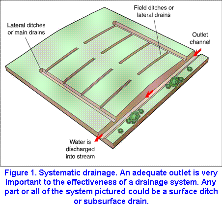
 To meet its design requirements, a drainage system must have an outlet of adequate capacity, depth, and stability (Figure 1).
If the outlet is inadequate, the effectiveness of the entire drainage system can be greatly reduced or lost. An outlet channel must have the capacity to carry flow not only from the drainage system but also from the entire area served by the system. Where the outlet carries flow from subsurface drains, the outlet should be deep enough that the drains can be discharged into it above normal low-water flow.
Installation of an outlet channel or improvement of an existing channel usually increases peak discharge downstream from the end of the improvement. Take steps to prevent increased stages downstream from creating significant damage. The channel must be stable when flow reaches design capacity. Where the drainage area exceeds 1 square mile, consult Design of Open Channels , Natural Resources Conservation Service Technical Release no. 25, U.S. Department of Agriculture, Washington, D.C., October 1977. This publication contains procedures for evaluating channel stability.
Design Considerations
Capacity
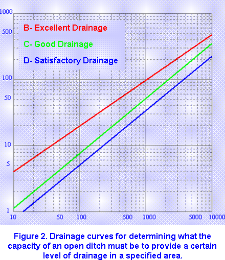 Crops can tolerate a limited amount of flooding or ponding but should normally not be flooded or ponded for longer than 24 to 48 hours. To determine what the capacity of the outlet channel must be to remove water quickly enough, either calculate flood routings of the drainage area or refer to drainage curves like those shown in Figure 2.The curves show the rate of discharge that will provide a certain level of drainage in the watershed area. They were developed from many field measurements of drainage flow rates and from observation of drainage systems. The curves are applicable only to drainage areas having average slopes of less than 25 feet per mile and do not allow for peak flows after heavy rains. Excess runoff will be discharged overland, temporarily flooding adjacent areas.
Outlet channels designed according to curve B will provide excellent agricultural drainage in Illinois . Use this curve for drainage of truck crops, nursery crops, and other specialty crops. Designs based on curve B will provide the best drainage that can normally be justified in agricultural areas. Channels that are designed according to curve C will provide good agricultural drainage in Illinois . This curve is the one most often recommended for drainage of Illinois cropland. Designs based on curve D provide satisfactory agricultural drainage as long as frequent overflow does not cause excessive damage. This curve is generally recommended for pasture or woodland. It may also be adequate for drainage of general cropland in northern Illinois , provided that the landowner carries out an excellent maintenance program. Designs based on curve D provide the minimum amount of drainage recommended in Illinois . The Ditch Sizing Routine progam can be used to determine ditch capacity based on these curves.
Once you know what the capacity of the outlet channel must be, you need to determine the size that will enable it to convey the desired amount of flow without letting the water surface rise above a predetermined elevation. The following sections describe some basic hydraulic concepts that will help you design a channel of the proper size.
Velocity
The velocity of water flow must be high enough to prevent siltation in the channel but low enough to avoid erosion. Listed on the next page are the maximum velocities for drainage areas of 640 acres or less. The velocity should be no lower than 1.5 feet per second. A lower velocity will cause siltation, which encourages moss and weed growth and reduces the cross section of the channel.
| Soil Texture | Maximum Velocity
(ft/sec) |
| Sand or sandy loam | 2.5 |
| Silt loam | 3.0 |
| Sandy clay loam | 3.5 |
| Clay loam | 4.0 |
| Clay or silty clay | 5.0 |
| Fine gravel, cobbles, or
graded loam to cobbles |
5.0 |
| Graded mixture silt to cobbles | 5.5 |
| Coarse gravel, shales,
or hardpans |
6.0 |
Hydraulic gradient
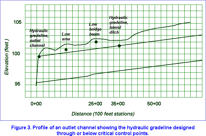 The hydraulic gradient represents the surface of the water when the outlet channel is operating at its design flow (Figure 3).The hydraulic gradient for the channel should be determined from control points such as the elevation of low areas served by the channel and the hydraulic gradients of tributary ditches. Draw the hydraulic gradient through or below as many important control points as possible after studying the profile of the natural ground surface, elevations established by surveys, and channel restrictions such as culverts and bridges.
If you estimate the elevations of control points rather than compute them from survey data, the hydraulic gradeline should be no less than 1 foot below fields that will receive runoff from ditches draining more than 640 acres, 0.5 foot for ditches draining 40 to 640 acres, and 0.3 foot for ditches draining less than 40 acres. For lands planted in only water-tolerant vegetation, such as some trees and grasses, these requirements may be modified and the hydraulic gradeline set at ground level. These guidelines do not apply to channels where flow is contained by dikes.
Manning’s equation
The most widely used equation for designing outlet channels was developed by Robert Manning in 1890 and is known as Manning’s equation:

where
V = average velocity of flow (ft/sec),
n = coefficient of roughness,
r = hydraulic radius (ft),
s = slope of hydraulic gradient in feet per foot (although s should be the slope of the water surface, it can be the slope of the channel bottom for designs within the scope of this publication).
The equation below is used to determine r:
r = A/P
where
A = area of cross section in square feet,
p = wetted perimeter or length, in feet, of cross section on which water impinges.
The roughness coefficient n takes into account not just roughness, but anything in a channel that might retard the flow of water. Vegetation, meanders, obstructions, etc., all affect channel flow. For designs within the scope of this publication, a value of n = 0.04 is commonly used if the channel has aged. Many tables used in channel design are based on that value. However, in determining a value for n, you should consider all retarding influences, not just aging. Select a value representing conditions that will exist after the channel has aged and that assumes the amount of maintenance you expect to do.
Generally, n tends to decrease as the hydraulic radius increases. Listed below are recommended values for n based on the hydraulic radius of the channel. You can use these values in solving Manning’s equation if the channel has good alignment.
| Hydraulic Radius
(ft) |
Roughness
Coefficient |
| less than 2.5 | 0.040 – 0.045 |
| 2.5 to 4.0 | 0.035 – 0.040 |
| 4.1 to 5.0 | 0.030 – 0.035 |
| more than 5.0 | 0.025 – 0.030 |
After determining V, calculate channel capacity, using the continuity equation:
![]()
where
Q = capacity in cubic feet per second,
A = area of cross section in square feet,
V = velocity in feet per second (determined from Manning’s equation).
The Manning’s Equation program can be used to solve Manning’s equation for several channel shapes. The program can be used for irregularly-shaped channels if the channels can be represented by 7 points with known elevations.
Channel depth
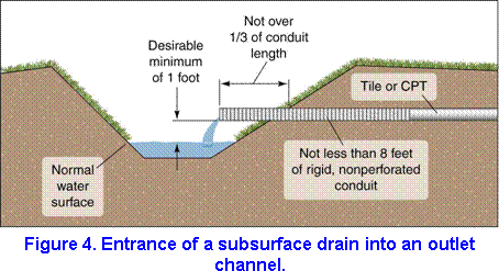
An outlet channel that receives water from subsurface drains should be designed to keep the normal water surface 1 foot below the bottom of the subsurface drain (Figure 4). The normal water surface is defined as the elevation of the usual low flow during the growing season. The clearance may be less where there are unusual site conditions.
Cross section
The design cross section of the outlet channel should meet the combined requirements of capacity, velocity, depth, side slopes, and bottom width, and, if necessary, allow for initial sedimentation. The side slopes should be stable, meet maintenance requirements, and be designed according to site conditions. In silt, the side slopes should be no steeper than 2 to 1; in clay and other heavy soils, 1 1/2 to 1; and in sands, peat, and muck, 1 to 1.
Construction equipment and maintenance requirements influence the width of the bottom of the channel and should be determined according to the conditions of the site.
Other Considerations
Location and alignment
If possible, the outlet channel should be located near or parallel to field boundaries or property lines where it will not interfere with cropping patterns. It is even more desirable to place it along existing natural drainage courses to minimize excavation.
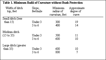
We recommend that you lay out the channel in straight lines and gentle curves. Table 1 lists recommended minimum radii of curvature for channels without bank protection. Provide bank protection if changes in alignment are sharper than those listed in the table.
Berms and spoil banks
Excavated soil may either be spread or placed in spoil banks along the outlet channel. If you place the soil in spoil banks, also leave a berm or flat area adjacent to the channel bank for the construction of roads and operation of maintenance equipment.
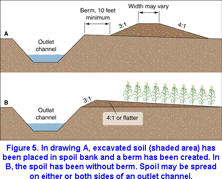
Berms will also prevent excavated material from rolling back into the channel and lessen sloughing of the banks by reducing heavy loads on them. Berms should be at least 10 feet wide, and, if the channels are over 8 feet deep, they should be 15 feet wide (Figure 5a). Make sure that the side slopes of the spoil banks are stable and adequately shaped to permit establishment and maintenance of vegetation. Provide some means by which water can flow through the spoil and into the ditch without causing erosion.
On cropland it is often desirable to spread the spoil. Begin spreading at or near the channel bank or leave a berm as described above. If you begin spreading at the channel bank, carry the spoil upward at a slope no steeper than 3 to 1 to a depth no greater than 3 feet. From the point of maximum depth, the spoil should be graded to slope away from the channel no steeper than 4 to 1 and preferably 8 to 1 if the spoil is to be farmed (Figure 5b).
Junctions of lateral ditches
Where there is a significant drop from a lateral ditch to the outlet channel, the lateral should be cut back on a level grade and then graded back on a slope (Figure 6a).
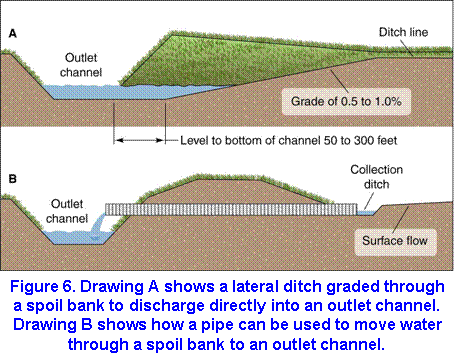
The purpose of this level area is to store sediment and protect the channel until the lateral stabilizes. Excavate the lateral on a level grade flush with the bottom of the outlet ditch for a distance of 50 to 300 feet. Then, steepen the lateral grade from 0.5 to 1.0 percent until it intersects the normal grade of the lateral. Where the drop from the lateral to the channel is too great to be controlled by the above method, you will have to provide structural protection.
Structural protection
Ideally, surface water should enter the outlet channel only through lateral ditches graded to the bottom of the channel (Figure 6a) or through stabilizing structures such as chutes, drop spillways, or conduits with proper inlets (Figure 6b). These structures may be located at the entrances of lateral ditches, at the heads of outlet channels, or along the outlet channel at selected intervals.
Culverts and bridges
When designing culverts and bridges across ditches, carefully determine the load from the weight of farm machinery, trucks, and other vehicles expected to cross them. Designs should facilitate ditch maintenance around the abutments, and the openings must be large enough not to reduce ditch flow capacity. Where it is not possible to construct bridges and culverts, you can build fords with ramps for livestock and machinery.
Effects on environment
In most cases, you can build and maintain an outlet channel that will accomplish its purpose as well as contribute to the environment. For example, if a dense tree canopy is situated on the site of the channel, you can carry out construction from just one side of the channel. The canopy remaining will shade the channel for at least part of the day. The favorable effects of the tree canopy will be to provide a windbreak; increase the fishery potential of the channel by keeping the water temperature lower than if the channel were unshaded; provide an area for wildlife between the cropped area and the water; and create a pleasing esthetic effect on land that might otherwise have been committed entirely to agricultural use.
Delay mowing in the channel and on maintenance travelways until the ground-nesting species of wildlife have departed, which is normally after the middle of July. Areas along the channel that are not used for travel or farming can be planted to shrubs, trees, or other plants that provide food for wildlife.
Maintenance
Maintenance of a drainage system is the key to lengthening its life and lowering operating costs. In any proposed drainage project, you should begin thinking about maintenance requirements as early as the design stage. We strongly recommend a systematic, annual inspection and maintenance program.
Seeding outlet channel banks to permanent cover will prolong the life of many channels by helping to stabilize the banks and by reducing weed infestations. Maintain a 10-foot grass strip along the channel to reduce erosion and provide access for maintenance. Brush and weeds reduce the velocity of water flowing in the channel, limiting its drainage capacity. Short-stemmed grasses are preferred since they provide a smooth surface for water. The grass on channel banks, berms, and spoil banks may occasionally need mowing. When you mow, be careful to avoid destroying wildlife. Brush and weeds can be controlled by herbicide sprays. Always check local, state, and federal regulations on the use of herbicides, and be sure to follow the instructions on the herbicide label.
Aquatic weeds should be kept out of channel bottoms since weeds limit drainage by reducing flow rates and causing sediment to deposit. Although these weeds can be controlled with herbicides, whether you may apply them will depend upon downstream uses of the water and your legal liability. Be sure to investigate your legal liability before applying herbicides. Sediment deposits and accumulations of debris should be removed from outlet channels to maintain their design capacity.