Laboratory experiences, ideally, should be hands-on and intellectually stimulating. When I first began managing the ME 310 laboratory in 2014, we had a friction losses in pipe flow experiment that was fairly uninteresting. It was a canned experiment on a small scale. Students found it boring.
As I started thinking about ways to improve the lab course, this lab exercise was first on my list to improve or replace. I wanted to make a lab exercise that was both fun and challenging. Given that ME 310 is a required course in the Mechanical Engineering major, I wanted to add design elements as well. I conceived of an experiment where students would build an open-circuit pipe network that fed two fountains. A single fixed-head reservoir would supply water to the fountains, each of which had unique performance goals. The only way that students would be able to succeed in the design project would be if they performed high quality empirical measurements and also careful and detailed mechanical analysis. I also wanted students to begin to see the consequences of limited precision and accuracy in order to develop a practical appreciation for experimental uncertainty.
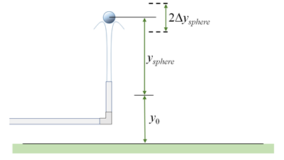
A colleague told me about a video that Professor Roberto Zenit showed at the APS-DFD conference in 2013 where he demonstrated near-vertical water fountains supporting plastic spheres stably and repeatably. With this video as inspiration, I developed a four-week design project to close out the semester in the lab course. Student teams must build a fountain systems where two fountains run simultaneously. One fountain (the “Supporting Fountain”) must support a plastic sphere at a designated target height. The other fountain must hit a circular target a specified height and distance away with a specific flowrate. Students are not allowed to use valves.

The electronic circuit analogy to this problem is simply two parallel circuits where the goal is to achieve a specific current through each branch. The fluid mechanics problem, however, is much more complicated to solve. Students are not allowed to test multiple iterations of a pipe network. They are required to test each component uniquely, according to the following schedule.
Week 1: Students do empirical testing of the Supporting Fountain
Week 2: Students do empirical testing of major losses in the straight segments of the pipe. They are required to plot their data points on then Moody diagram.
Week 3: Students do empirical testing of minor losses in non-uniform components such as elbows, U-bends, reducing straight connectors, and reducing elbows. They will measure the loss coefficient for each component as a function of Reynolds number.
Week 4: Students are required to come to the laboratory with a full technical report that summarizes the results of the previous three weeks, as well as a complete design of their proposed fountain network. They build the network in the laboratory and then their TA tests its performance. Students then have one week to write an engineering letter report that summarizes the results of the testing. If their fountain system did not perform correctly, they are required to diagnose the reason it failed and propose a proper correction.