
Tensegrity structure was invented simultaneously in different part of the word. R. Buckminster Fuller applied for the patent in the U.S around 1960’s and referred it as “Tensile Integrity”. Meanwhile, D.G. Emmerich applied for the patent in France and named it “Peral Frameworks”. In 1965, K. Snelson applied for the patten and named “Continuous tension, discontinuous compression structure” (Motro 2003).
A tensegrity structure is lightweight and has a flexibility that can compose to create a different shape. Tensegrity structure based on a system of isolated components under compression inside a network of continuous tension and arranged in such a way that the compressed members (usually bars or struts) do not touch each other while the prestressed tensioned members (usually cables or tendons) delineate the system spatially. Because of these patterns, no structural member experiences a bending moment and there are no shear stresses within the system. This can produce exceptionally strong and rigid structures for their mass and for the cross-section of the components.
Motro (2003) introduced different types of Tensegrity structure. Among different types tensegrity system, the TIE for Rhino is developed to deploy two of tensegrity system. Which are “Simplex” and “Rhombic (diamond) system.”
- Simplex System
A Simplex Structure is based on triangle pattern. The top side triangle connects with the bottom side triangle with cables and struts. As shown in figure 1, it compose with 9 cables and 3 struts. Our idea is set one system as a unit (module) and array this units to create a bigger structure.
![]()
Figure 1. Basic configuration of simplex system
As shown in figure 2, when 2 units combine, 4 cables and 1 strut can be shared. This shows that it is possible to combine the units together and become a structure group.
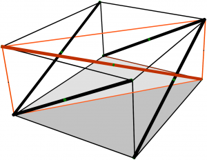
Figure 2. combing two simplex system (red indicate sharing cables and strut)
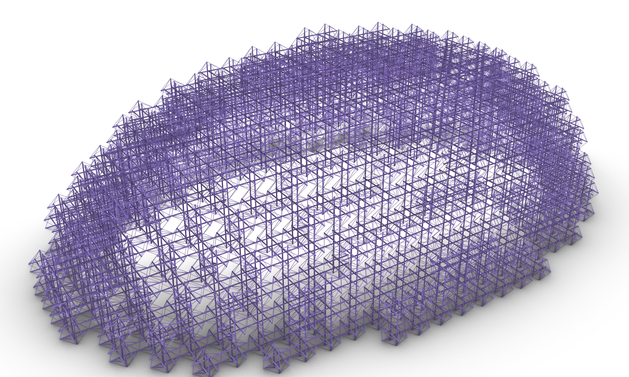
Based on this logic, if top and bottom side surface are designed, and divided to triangle patterns, simplex structure can be applied to construct shape (figure 3).
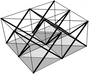
Figure 3. Combing 8 simplex system
2. Rhombic system
Same concept can be applied to different tensegrity structure, another system can be Rhombic (diamond) system. Figure 4, shows, one pair of the struts are parallel to each other on the same plane and being rotated in three-dimensions on X,Y,Z axis. Also, the volume of the Rhombic structure is a cube (Figure 5). With this discover, changing the size of the cube can change the size of the structure.
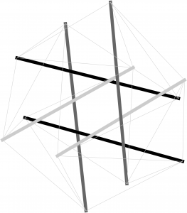
Figure 4 Basic configuration of Rhombic system
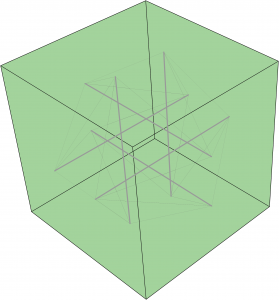
Figure 5, One rhombic system can encapsulated in a box
The end points of each strut are also the nodes of the structure to connect with the cables. When more than one unit combine, the nodes can shared with other units as the figure 6 shows. With this discover, the numbers of unit can be customized on X,Y,Z direction based on a given volume.
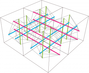
Figure 6. Combing 4 rhombic system
*Motro, René. (2003) Tensegrity : Structural systems for the future, London Kogan Page Science, https://doi.org/10.1016/B978-1-903996-37-9.X5028-8.