Introduction
In this MP, you are going to implement an RRT path planner for an autonomous car. In the first part, you will learn to implement a simple controller for maneuvering the car from point A to point B. In the second part, you are going to integrate this controller in the RRT path planning algorithm.
Installation and Setup
Unlike all other MPs, you are not going to implement this assignment using a jupyter notebook, but you will be editing python scripts. Clone the assignment repository:
git clone https://gitlab.engr.illinois.edu/GolfCar/mp5-release
cd mp5-release
In this particular assignment, you are going to specifically edit two files which are listed below:
- controller/controller.py (See Controller synthesis section)
- RRT.py (See RRT section)
Control Synthesis
Dubin’s model of the car
In the control synthesis part of the Machine Problem, you first have to design a controller which takes the car from point A to point B. Before synthesizing the controller, we first need to come up with the control model (or dynamical model) of the problem.
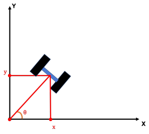
For newbies here, a control model is the sensitivity of the change of state of the car (for example position) with respect to the control inputs, which in this case is the thrust (\(V_R\)) and steering angle (\(\delta\)). There have been many proposed control models of the car but as far as this MP is concerned we are going to use Dubin’s Model for the car which is as follows,
$$\begin{bmatrix}\dot{x} \\ \dot{y} \\ \dot{\theta} \end{bmatrix} =\begin{bmatrix}V_R \cos(\theta) \\ V_R \sin(\theta) \\ \delta \end{bmatrix}$$
Now, you are going to implement a controller to drive the car from point A to point B.
One possible algorithm to do this you will have to first correct the heading of the car so that the heading angle of the car is equal to the angle made by the vector \(\vec{AB}\) with the x-axis. After this heading is aligned, you simply need to drive straight toward point B. This control strategy is described below. While this method generally works well, you may also implement your own controller, if you’d like.
Controller Algorithm
Initialise: \(\epsilon > 0, K > 0, V_R\), \(B = (x_d, y_d)\), \(A = (x, y, \theta)\)
\(\quad alpha = arctan((y_d – y)/(x_d – x)) – theta\)
\(\quad \textbf{while} (|alpha| > \epsilon):\)
\(\quad \quad \delta = K*(alpha)\)
\(\quad \quad (x, y, \theta) = model(\delta, V_R = 0.0)\)
\(\quad \quad alpha = arctan((y_d – y)/(x_d – x)) – theta\)
\(\quad \textbf{end while}\)
\(Dist = \sqrt{(x_d – x)^2 + (y_d – y)^2}\)
\(Time Steps = \frac{Dist}{V_R*0.05}\)
\(\textbf{For i = 1 to TimeSteps}\)
\(\quad (x, y, \theta) = model(\delta = 0.0, V_R)\)
\(\textbf{end for}\)
Implement your controller in the blanked out portion in controller/controller.py in the gitlab repository. You can test your implementation by running the test function in the controller.py file.
Once your controller is working, you will then need to implement the RRT path planner as described in the next section.
RRT
RRT algorithm was proposed by our own U of I Prof. Steve LaValle and Dr. James Kuffner in 1998 as an efficient search algorithm in non-convex spaces. RRTs were later demonstrated to handle differential constraints so well that roboticist started using this in Autonomous Motion Planning. In this part of the MP, you are going to implement a RRT path planning algorithm for a self-driving car. RRT algorithm is described in detail below.
Rapidly-Exploring Random Trees Algorithm
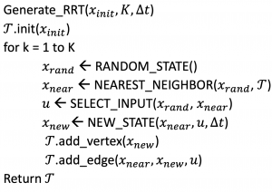
After the full run of the RRT algorithm, an example reconstruction would look something like this:

Summary
In this MP, you are first going to implement a lower-level controller for a self-driving car (controller/controller.py). Using this controller to reach waypoints, you are going to implement the RRT algorithm in RRT.py file.
After completing the implementation of the RRT algorithm, you need to write a concise report answering the following questions:
- Complete your implementation of the RRT algorithm and run this on the two world maps provided to you; ‘maps/fourway_intersection.jpeg‘ and ‘maps/single_road.jpeg‘. Create a RRT graph implementation as shown in the gif above for 100 iterations.
- You saw in the file RRT.py that the points in the map is sampled uniformly with a minimum grid size of 10 pixels. Trying running your RRT code on with fineness of 1 pixels and fineness of 100 pixels and observe the results. Run this code for both the World maps ‘maps/fourway_intersection.jpeg‘ and ‘maps/single_road.jpeg‘
- Instead of the sampling mentioned in the RRT code, try implementing a goal based sampling. Does the code converge faster in that case? Why/why not ?
- Do you think that RRT always produces a ‘safe’ path? Why or why not ?
Grading Evaluation
- Controller Implementation (40%)
- RRT implementation (40%)
- Completing the project report with question responses (20%)