Project Update: Smart Glove

With the deadline fast approaching, I’m glad to say we have a fair amount of work done and we also have a good plan moving forward. For what we’ve done so far, We have a basic prototype with a force sensor done. This consists of the glove and two copper sheets isolated by some flexible material. Each layer is further isolated by the black hockey tape you see in the picture. Also, we are currently prototyping on an Arduino Uno, but for the final design we’d like to use an Arduino Nano (which should be a drop in replacement).

IMG_20160424_233634144

One of the biggest design changes we made this week was realizing that it would be unnecessary to process all the data in real time on the Arduino, and it would be better to just use it to capture the raw data and process it later on a computer. One potential idea we had was to make a small website to do it, and time permitting, we’d like to try that out.

Moving forward this week, we need to design the sd card system, which should be fairly trivial, and see if it is still feasible to do the accelerometer.

The Uncanny Valley

This week we ventured into the world of 3D scanning and took scans of ourselves from the shoulders up. Honestly, my mind was blown. I had no idea that something so detailed could come from an iPad and a $300 add on. What I thought was even more interesting was that apparently the hardware inside the scanner was just a reworked version of the Xbox Kinect.

The scanning process was simple enough. One person sat in a chair and the other person walked around them to capture from all angles. Then the point cloud (the raw data coming off the sensor) was sent to a server in the cloud to be fully processed, and the final model was then downloaded back to the device. The whole process took less than five minutes. After getting the scanned model, all we have is a starting point. It very likely has some errors in it due to noise from the scan, and it’s our job to clean it up. We used a program called Meshmixer by Autodesk that had lots of great features for cleaning up the scan.

Unfortunately, I don’t have any pictures of my scan, but it actually turned out fairly decent. There was just one major flaw on the back of my head where my hairline brushing up against the collar of my jacket messed it up, but it was relatively easy to fix.

Once it was all cleaned up and ready to print, I took a good look at it, and the model was definitely in the “Uncanny Valley”, a term used to describe objects that look almost human like, but are just artificial enough to be creepy. It was honestly a bit disconcerting to look at a full 3D rendering of myself. However, I feel that as this technology improves and the scans get closer to real life, people will stop viewing a 3D model of themselves, and look at it as more of a “3D picture”. There are so many great applications for a cheap, accurate, full body 3D scan. From inserting yourself into your favorite movie or video game, to a doctor being able to remotely diagnose a whole host of ailments, the applications are boundless.

FAB Lab, Round 3

This week was our final day (as a class at least) at the FabLab, and I was doing the last of the three stations, Digital Embroidery. Now, I’ll be completely honest, this was the station that I was least looking forward to. I feel at home when writing code or building circuits, but embroidery? That sounds too close to art class for me. But my problem was that I failed to see all the uses of this technology.

As our exercise, we made patches of images we found online. I went with my tried and tested Raspberry Pi logo, and I added a circular border. Once loading the design onto a flash drive, I took it over to a digital embroidery machine (which is surprisingly similar to a 3D printer) and started making it a reality. The whole process went pretty smoothly, and I even managed to thread the machine (after a few failed attempts). The final result had a few gaps, but I was able to color them in with a sharpie.

IMG_20160411_245318574

While the patch is nifty, and has earned a permanent place on my computer, I barely scratched the surface of what we could do. The machine can actually make fairly intricate designs, and with the slew of the new types of conductive fabrics, there are so many possibilities for wearable devices, and not just entire computers crammed onto your wrist, but real pieces of clothing. An entire shirt could be a circuit that would have embedded sensors. An idea I had would be for a onesie for an infant. The garment could have some sensors embedded and a tiny bluetooth module that would be the size of a button, all part of the clothing, that could alert the parent’s phone when the baby needs attention. The possibilities are really endless, and this tech could let us interact with wearables in a whole new way.

Build-A-Printer

This week was arguably one of the most interesting weeks of the course. It was the “Build a 3D Printer” event hosted by Ultimaker.While the main focus of the event was to build a 3D printer kit, I, along with Toheeb, Reid, and Elaine, instead working on upgrading one of the printers from the to the Ultimaker 2+ (from the regular 2). This upgrade consisted of a completely new extruder and feeder assembly, along with new quick release clips on the bed. According to the rep from Ultimaker at the event, the 2 was such a popular printer and there were only minor problems people faced, it made more sense for an incremental improvement instead of unnecessarily overhauling the design. The 2+ was this improvement, and all existing Ultimaker 2’s are upgradable.

The actual upgrade process revealed a lot about the inner workings of the printer since we had to disassemble it fairly significantly. We got to see all the stepper motors and actually replaced the one used for the feeder. Then we pulled the entire extruder assembly off and installed the new one, and connected it to the logic board. The most surprising part of the whole process to me was how upon removing the logic board I saw that the microcontroller used was an ATMEGA328P, the same one used in an Arduino. (Meaning that the board was essentially a custom, special purpose Arduino). Talking with the rep Mark, I learned that the firmware was actually open source, and theres a pretty healthy community of modders writing custom firmwares for the platform. The board actually supports more connections that the printer uses, so there’s a lot of interesting functionality that could be added.

Overall, I feel that this exercise provided great insight into the actual workings of the printer, and the design ideology that goes into it. This device is made for makers, and as such, is meant to be tinkered with. It’s not just a black box that turns STL files into a physical object, but rather a platform that encourages you to tailor it to your specific needs.

Fab Lab: The Sequel

This week at the fab lab, I was at the Arduino station. Admittedly, this was not the first time I had used an Arduino so I was under the impression that it was going to be a pretty slow afternoon, but I quickly realized that would not be the case. After the ubiquitous blinking led and motor tutorials, we put together a rudimentary capacitive touch sensor. Talking with Colton, who was leading the workshop, we quickly realized this could be utilized to build a force sensor. That started an afternoon of experimentation where we tried to come up with the best way to design the sensor by experimenting with different materials to keep between the copper pads and whether insulating the pads had any effect. Our final design had us using a 6.8 megaohm resistor and a piece of (iirc) DMX foam between the two copper pads. The foam is extremely dense so it does not fully compress under normal force, which would have the effect of “topping out” our sensor, a problem we were having with other foams. Also, the pads worked best when surrounded by Mylar bags (to insulate from other some other electrical interference) and when one pad was connected to the resistor and the other was grounded. We also soldered wires to the copper to keep the thickness uniform, since that was a problem with alligator clips.

IMG_20160313_234931665_resized

This is a very rough first iteration. For starters we have no calibration on the device. The raw data we get is useful for relative measurements, but cannot give us an accurate representation of how many grams, Newtons, etc of force is being applied. To do that we would need to put the device on a scale and apply some known loads to it and then scale our raw data to that. Also, I suspect that the foam does not compress linearly, so we will have to do some research on the properties of the foam. Overall I’m very happy with the progress we made and I’m optimistic about the project as a whole.

Fab Lab Day 1

This week was our first of three days at the Champaign Urbana Fab Lab. The three stations that we will be working on are Digital embroidery, Arduinos, and laser cutting. This week I worked on the last of the three, laser cutting. We started out with the basics and took an image off the internet and converted it into a vector drawing, which led us into a quick discussion of the differences between a vector and a raster. We then went to the lasers and saw how they worked and went over the safety precautions to be taken.

We where then left on our own to design/convert our own design to laser cut or etch. I found a piece of red acrylic that gave me the idea of printing out a raspberry pi logo. So I found a logo online and it was surprisingly easy. The built in tool in Inkscape to convert a bitmap to a vector image worked perfectly and before I knew it I was cutting the acrylic! IMG_20160306_233430640

Even though this was a fairly simple design, I made a small mistake when exporting the file for printing in that I placed it too close to the edge of the page. You can see on the left side of the figure there is straight line. I failed to realize that you want to place the design a bit away from the edge because there is some imprecision to where the laser starts (that is, the top left corner of the material you are cutting is not always right under the starting point of the laser).

I feel that this technology is very complementary to 3D printing. Whereas 3D printing lets you create an endless amount of shapes, laser cutting lets you use very different types of materials, and at larger scales is much more cost effective than 3D printing, not to mention faster (my figure took less than a minute to cut, whereas 3D printing it would have taken in the one hour range). As we go on in this class I think that it is important that we not limit ourselves to 3D printing and think if our design could be made more economical by cutting.

Week 5: Fusion

These past two weeks have been a crash course into 3D modelling, and even from this brief intro, I can see that it is an extremely powerful skill. We started out with going over the basic tools and making random shapes, but if you showed me the lamp I’d be making in a weeks time, I wouldn’t have believed you. Even if I only retained half of what we went over (which is a lot closer to the truth than I would like) I still would have skills that greatly increase my capacity for making.

The first “real” object I made in Fusion was a simple bolt, but even then, I didn’t expect it to be as intricate as it did. The biggest thing that surprised me was how every hard edge was rounded out some how. Even though I’ve never actively thought about it, pretty much everything you touch is rounded to some degree, and that was a conscious decision that someone made.

bolt

The next week, we went through a guided tutorial on how to make a lamp, and this was the first time I had gotten really intricate with Fusion. Even now, looking back on what I made, I don’t entirely believe it. I always thought that 3D modelling was a black art of sorts, but in reality it’s extremely intuitive. It’s a lot like programming, something I’m very familiar with, but for physical objects. Programming is all about breaking a complicated process down to its individual steps, and modelling is about breaking down an object into its individual components. Now that I’ve seen how it works, I can’t wait to try more.

lamp

The next model I want to try an make is a raspberry pi case that also holds a breadboard. If you look on Thingiverse, plenty such models already exist, but my idea was to mount the breadboard upside down over the pi so that you could close the whole thing off into a small, low footprint box. The case would be in two parts so that during assembly the board would be right side up and the pi exposed, but then it would close up into a nice, clean package. I don’t anticipate too much trouble, especially since the exact measurements for the pi are everywhere online, but there’s always bound to be some unforeseen complications.

Week 3 Reflection

What?

This week we had a workshop led by Design for America. DFA is a student organization that focuses on solving real world problems with well designed solutions. The workshop started out with a high level overview of what it meant for something to be well designed and the steps involved in properly and efficiently designing something. I’ll admit, when these steps were first presented to me, I thought that they were fairly simplistic and even if not explicitly followed, most people would implicitly follow them in some capacity. However, as the workshop continued, I would see the value of them and how their simplicity was their greatest strength. I thought the most telling graphic they showed was one that described how they actually are constantly in multiple steps of the design process, and are constantly iterating and improving.

So What?

The second part of the workshop involved us designing a solution for one of four scenarios that involved a blind person in Austin, Texas. The problem my group tackled was one of a college student who felt that she wasn’t able to participate in the “university experience” due to her disability. When we began, we immediately started coming up crazy devices that would help her navigate a crowd and what not, but we quickly realized we weren’t really addressing the problem. The girl said she had been blind since childhood, so she definitely knew by this point how to manage herself day-to-day. The key to socially integrating into a big group like a University is to connect with people. We felt that the key was for her to meet some people she was comfortable around. We switched gears to create a service that would connect blind students with other students, a service along the lines of Friendzie or Tindr. We also found a really cool device called the Blitab, a Braille tablet for the blind, that we thought we could use to make the service more accessible. We felt that since at the core this was a social problem, we needed a social solution.

Now What?

I felt that this workshop was an extremely eye-opening experience. The biggest thing I took away from it was that when coming up with a solution for a problem, you need to be aware of the perspective of the user, and try and remove your personal biases. While that may seem obvious, it really is the hardest part of designing something, especially if it’s something where you’re not the target user. Even in such a short, simulated exercise, I found that keeping your perspective correctly aligned was the key to finding a solution to the problem. In the future, I feel that I will need to keep that in mind to find meaningful solutions to whatever problem I decide to tackle.

Week 2 Reflection

Reading Dale Dougherty’s The Maker Mindset, I realized that I had never really realized how the idea of making had become such a niche field. While the abilities of “amateur” makers today are greater than ever, fewer and fewer people are participating. After mulling over these thoughts all week, I think I believe this is due to two main reasons. One, as Dougherty puts in his article, is that people, especially children, are engaging less and less in “experimental play” where they get a hands on experience as to how things work. I also think that another cause of this is that as American society has progressed, the idea of consumable or “use-and-throw” products has become more and more accepted. When was the last time you saw a TV repair shop? Or someone cutting wood to fix a broken table? While some people do, most are content with simply replacing instead of repairing. I think the solution has to come from education. From a young age children should be taught that they have the ability to fix and make things, and that the only limiting factor is their imagination, not what some market research group decides they will most likely buy. They should learn to be builders, not buyers.

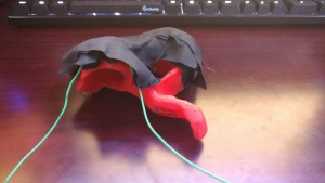
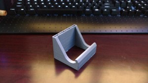
I’m now an adult in my junior year of college, and I’m only just now learning about things like 3D printing, Even from the crash course intro that I had this week, I can already say that my horizons have been greatly expanded. Case in point, a simple problem I have is that when I sit at my desk, I find it difficult to glance at my phone to see if I have any notifications. About five minutes on Thingiverse.com and I found this. And about an hour later, I had this:

IMG_20160207_231753417

I think it is just incredible that a model on my computer can all of a sudden become a physical object, and as we learned in the previous week’s implication, the impact is nearly immeasurable.

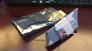
After I went home, I started thinking about other problems I had that could be solved by 3D printing, and one immediately came to mind. I have LED light strips like these hanging in my room, and one of the biggest problems is that almost half of their light output gets wasted on the ceiling. It would be much more effective if the lights were at a 45 degree angle pointing into the room, but most off-the-shelf solutions I’ve seen are meant to be screwed into the wall, a luxury I don’t have living in a student apartment. So I thought, what the heck, and tried to create something on Tinkercad that would allow me to mount the light clips at an angle, while having a large, smooth base I could stick to the wall with command strips. This is what I came up with. While it won’t win any design awards, it solves a very specific problem that I had for which there was no mass-market solution. I printed one out as a test, though when I finally mount the lights with them, I’ll need upwards of twenty (only the gray part is 3D printed, the white part is a clip to hold the strip).

IMG_20160207_231841102

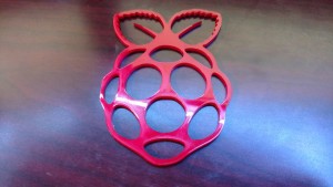
Browsing Thingiverse, I found several other designs that I think I could be very useful to me. One such thing would be this Raspberry Pi/Breadboard combo holder. It’s incredibly frustrating when there’s several wires running between the two, and then they accidentally get pulled out. This would keep them fixed together and avert that problem, and I like this design over others since it uses very little material. A small modification I would make though is to make the slot for the Pi a smidge larger, since some users are saying that it’s not a great fit.

Another interesting model I found was this headphone desk mount. It’s fairly self explanatory, but a great thing about this stand would be the fact that you can edit the model to be the exact thickness of your desk to ensure a perfect fit.

Back to the Raspberry Pi, this little enclosure will fit into a standard desktop computer 5.25″ bay, or some external enclosure, and can put a Pi and a 3.5″ hard drive to create a small file server. I think I would like to design a snug case to be able to take it on the go or dock it into a computer.

Week 1 Reflection Post

Listening to Mr. Hornick’s presentation this week, I felt like I was really seeing the future. I admittedly did not know much about the practical applications for 3D printing before hearing him, let alone the industrial applications, but I now realize that we are on the verge of a complete paradigm shift in the world of manufacturing. I think that the best way to sum up what Mr. Hornick had to say is that manufacturing will be democratized and localized. Today, the manufacturing industry is one that is dominated by the idea of economies of scale, and the more the better. 3D printing on the other hand has the benefit of a linear relationship between quantity and cost. Two widgets cost twice as much to manufacture as one.

An area of Mr. Hornick’s presentation that really caught my attention was that of brands. In the future, will people pay for the Nike design file, when the off-brand one is reportedly just as good and half the cost? The cost of the materials will be the same, since the consumer is providing them, and without that differentiation I feel that the contemporary brands that dominate the market will find it difficult to compete. Reflecting on the presentation later, I had the idea that open-source designs will become a big player much as they have in the world of software. Even today, so many 3D models are available for free, and I feel that as the technology matures, more and more collaboration and cooperation will result in a thriving world of open-source products from shoes to heart-valves, and the traditional brand names will need to find a stay relevant.

In the week since the presentation, I’ve spent more time than I care to admit looking at cool and interesting 3D printing projects on YouTube. One of the ones that really stuck out to me was this platform jack that is printed in one fully assembled piece. While it was very impressive that the design needed no assembly, I thought the more impressive part was that it was printed on an Ultimaker 2, the very same printers we have in the lab. In the video, he demonstrates how it can actually support the weight of a vacuum cleaner. This design demonstrates how a “hot glue gun on steroids” can actually be used to build really useful things.