
Transmission Electron Microscopy
Transmission electron microscopes are utilized for examining the interior structures of materials at high resolution and high magnification. The sample size for the TEM is restricted however to a 3 mm disk which is thinned to electron transparency. The TEM can be used to determine the crystal structure of materials as well as crystal faults. The TEM has been used to observe the basic structure of C-S-H, the major hydration product of portland cement.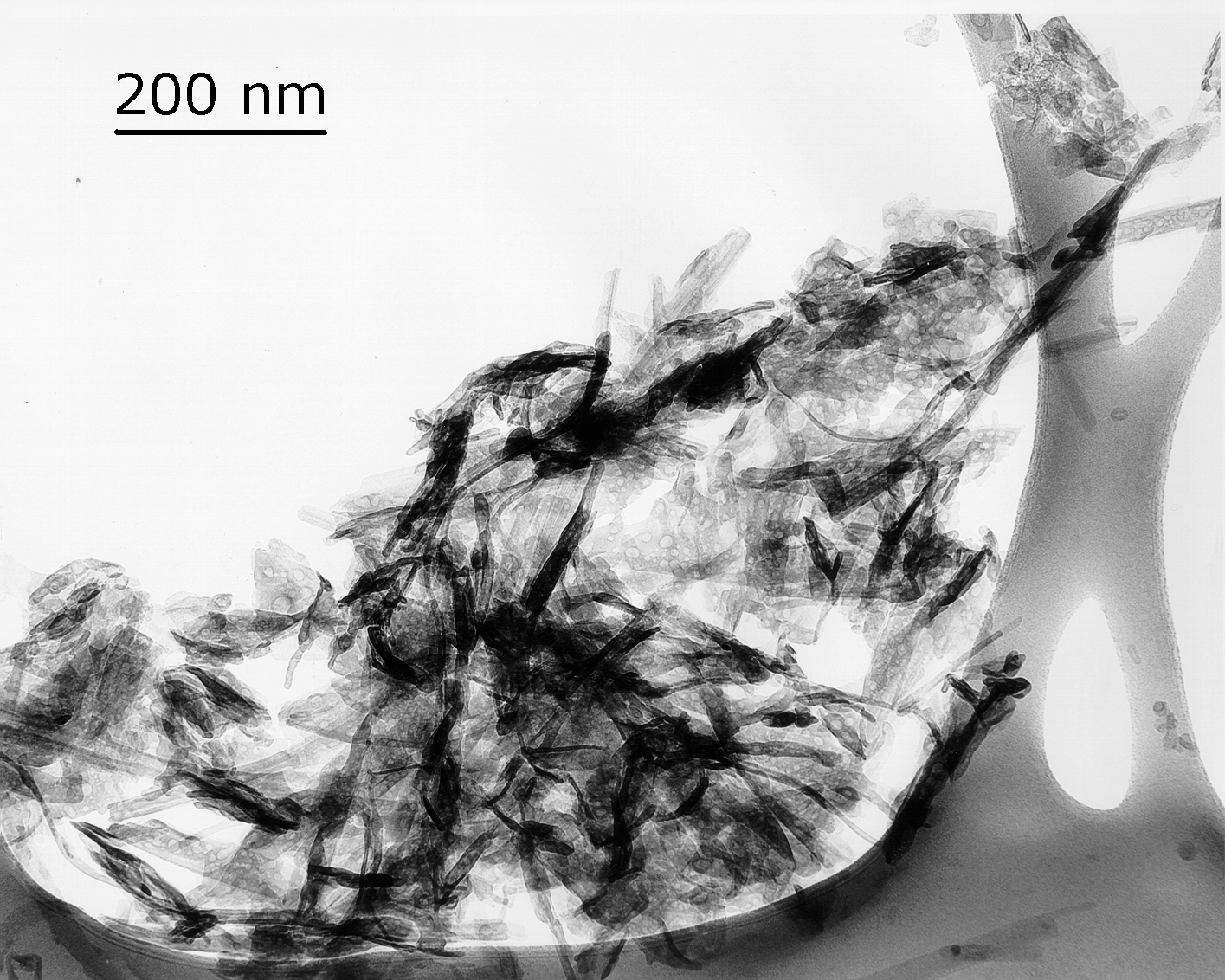
![The two TEM images above are of a synthetic C-S-H prepared by reacting Degussa Aerosil 300 with calcium hydroxide solution. This prep was aged for 24 months at 20°C in CO2-free water and shows the crumpled foil morphology typical of bottle-hydrated C-S-H. The background structure is the holey carbon support. [Credits: Dr. Eric Lachowski (email: e.lachowski@abdn.ac.uk), S.Y. Hong, and F.P. Glasser]](http://publish.illinois.edu/concretemicroscopylibrary/files/2014/04/CSH1.jpg)
The two TEM images above are of a synthetic C-S-H prepared by reacting Degussa Aerosil 300 with calcium hydroxide solution. This prep was aged for 24 months at 20°C in CO2-free water and shows the crumpled foil morphology typical of bottle-hydrated C-S-H. The background structure is the holey carbon support. [Credits: Dr. Eric Lachowski (email: e.lachowski@abdn.ac.uk), S.Y. Hong, and F.P. Glasser]
![This image is an argon-milled section of a slag-cement blend. On the upper right is normal cement paste C-S-H showing the morphology you normally get from alite hydration. On the lower left, on the other side of the interface is the product obtained from the hydration of blastfurnace slag. Right over in the left corner is an amorphous gel, while the needele-shaped particles at the interface are crystals of hydrotalcite. These are actually hex plates standing on edge. The orientation effect is strong and persists for years - it can be seen in SEMs of slag-cement blends as clusters of corn-flake-like particles. [Credits: Dr. Eric Lachowski, Q.L. Feng, and F.P. Glasser]](http://publish.illinois.edu/concretemicroscopylibrary/files/2014/04/SLAG.jpg)
This image is an argon-milled section of a slag-cement blend. On the upper right is normal cement paste C-S-H showing the morphology you normally get from alite hydration. On the lower left, on the other side of the interface is the product obtained from the hydration of blastfurnace slag. Right over in the left corner is an amorphous gel, while the needele-shaped particles at the interface are crystals of hydrotalcite. These are actually hex plates standing on edge. The orientation effect is strong and persists for years – it can be seen in SEMs of slag-cement blends as clusters of corn-flake-like particles. [Credits: Dr. Eric Lachowski, Q.L. Feng, and F.P. Glasser]