
Specimen Preparation
by Paul Stutzman, NIST
Introduction
Specimen preparation is important in any microscopical technique with proper preparation methods facilitating examination and interpretation of microstructural features. Improper preparation methods may obscure features, and even create artifacts that may be misinterpreted. Scanning electron microscope (SEM) analysis using backscattered electron and X-ray imaging requires a highly polished surface for optimum imaging. Rough-textured surfaces, including those produced using only saw-cutting diminish the image quality by reducing contrast and loss of feature definition. Additionally, the lack of a polished specimen makes quantitative estimates arduous, as the surface is no longer planar.
We have developed a series of preparation procedures in our laboratory at NIST. The procedures are used for Portland cement clinker, cement powder, cement pastes, mortars, and hardened portland cement concrete to allow clear definition of specimen features in SEM imaging [1-6]. An epoxy resin is used to permeate the material’s pore system or to encase powder particles. The specimens are then cut or ground to expose a fresh surface, and that surface is then polished using a series of successively finer grades of diamond paste. This polishing stage is necessary to remove cutting and grinding damage, and to expose an unaltered cross section of the material’s microstructure.
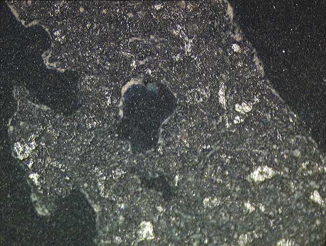
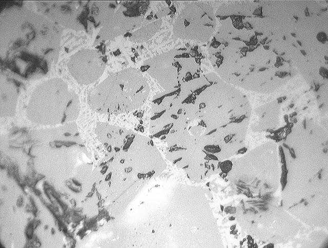
In contrast, concrete that has a saw-cut surface without epoxy impregnation exhibits little constituent contrast and substantial cracking (Figure 3). The loss of contrast may be attributed to the roughness of the surface and the cracking to both the cutting and tearing action of the diamonds embedded in the saw blade, and drying shrinkage-related cracking of a damaged microstructure. A cross-section of this preparation, after epoxy impregnation and polishing, shows the extent of cracking resulting from the saw damage and drying shrinkage (Figure 4).
Epoxy impregnation of the pore system serves two purposes: A) it fills the voids and, upon curing, supports the microstructure serving to restrain it against shrinkage cracking, and B) it enhances contrast between the pores, hydration products, and cementitious material. With relatively high permeability materials or powders such as clinker or portland cement, an epoxy of low viscosity is necessary while for the less permeable cement pastes and concretes an ultra-low viscosity epoxy aids in rapid infiltration of the pore structure.
![Figure 1. Polished section of Portland cement particles imaged using the backscattered electron signal shows the constituent phases. Ferrite appears brightest followed by alite, belite, aluminate, alkali sulfates, and periclase. Field width: 125 micrometers. [Paul Stuzman, NIST]](http://publish.illinois.edu/concretemicroscopylibrary/files/2014/04/figure1.jpg)
Figure 1. Polished section of Portland cement particles imaged using the backscattered electron signal shows the constituent phases. Ferrite appears brightest followed by alite, belite, aluminate, alkali sulfates, and periclase. Field width: 125 micrometers. [Paul Stuzman, NIST]
![Figure 2. 28-day old hardened portland cement paste microstructure. Image field width: 17 micrometers. [Paul Stuzman, NIST]](http://publish.illinois.edu/concretemicroscopylibrary/files/2014/04/figure2.jpg)
Figure 2. 28-day old hardened portland cement paste microstructure.
Image field width: 17 micrometers. [Paul Stuzman, NIST]
![Figure 3. A sawn-surface preparation imparts substantial damage, leaving a rough surface and residual particulate matter. Poor imaging contrast and shadowing result and make BE and X-ray imaging difficult. Lack of epoxy to support the microstructure results in drying shrinkage-related cracking. [Paul Stutzman, NIST]](http://publish.illinois.edu/concretemicroscopylibrary/files/2014/04/figure3.jpg)
Figure 3. A sawn-surface preparation imparts substantial damage, leaving a rough surface and residual particulate matter. Poor imaging contrast and shadowing result and make BE and X-ray imaging difficult. Lack of epoxy to support the microstructure results in drying shrinkage-related cracking. [Paul Stutzman, NIST]
![Figure 4. An edge-on view of the sawn-surface preparation (epoxy-impregnated and polished) shows the surface damage imparted by the sawing action as well as the depth of drying shrinkage cracking resulting from drying a specimen without prior epoxy impregnation. [Paul Stutzman, NIST]](http://publish.illinois.edu/concretemicroscopylibrary/files/2014/04/figure4.jpg)
Figure 4. An edge-on view of the sawn-surface preparation (epoxy-impregnated and polished) shows the surface damage imparted by the sawing action as well as the depth of drying shrinkage cracking resulting from drying a specimen without prior epoxy impregnation. [Paul Stutzman, NIST]
![Figure 5. A clinker surface after saw-cutting and grinding using 600-grit silicon carbide (right image) exhibits no discernible microstructure due to the rough surface. Increased polishing time (left image) using 6 mm diamond paste progressively removes grinding and cutting damage pits and begins to reveal the underlying microstructural features. [Paul Stutzman, NIST]](http://publish.illinois.edu/concretemicroscopylibrary/files/2014/04/figure6.jpg)
Figure 5. A clinker surface after saw-cutting and grinding using 600-grit silicon carbide (right image) exhibits no discernible microstructure due to the rough surface. Increased polishing time (left image) using 6 mm diamond paste progressively removes grinding and cutting damage pits and begins to reveal the underlying microstructural features. [Paul Stutzman, NIST]
![Figure 6. Continued polishing removes additional material of the damaged layer leaving fewer grinding pits as shown in the left image. The right image shows a specimen where all grinding pits have been removed and is now ready for the 3 micrometer and finer polishing steps to remove any fine scratches. [Paul Stutzman, NIST]](http://publish.illinois.edu/concretemicroscopylibrary/files/2014/04/figure8.jpg)
Figure 6. Continued polishing removes additional material of the damaged layer leaving fewer grinding pits as shown in the left image. The right image shows a specimen where all grinding pits have been removed and is now ready for the 3 micrometer and finer polishing steps to remove any fine scratches. [Paul Stutzman, NIST]
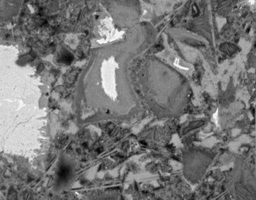
![Figure 7. Epoxy-impregnated, polished section of concrete presents an optimum surface for backscattered electron and X-ray imaging. [Paul Stutzman, NIST]](http://publish.illinois.edu/concretemicroscopylibrary/files/2014/04/figure9.jpg)
Figure 7. Epoxy-impregnated, polished section of concrete presents an optimum surface for backscattered electron and X-ray imaging. [Paul Stutzman, NIST]
![Figure 8. Backscattered electron (top) and X-ray (bottom) images of hardened cement paste show good definition of constituents. Regions of intermediate-intensity calcium (blue) and intermediate-intensity aluminum (purple), and high-intensity sulfur (yellow) define locations of monosulfoaluminate. Field width: 73 micrometers. [Paul Stutzman, NIST]](http://publish.illinois.edu/concretemicroscopylibrary/files/2014/04/figure11.jpg)
Figure 8. Backscattered electron (top) and X-ray (bottom) images of hardened cement paste show good definition of constituents. Regions of intermediate-intensity calcium (blue) and intermediate-intensity aluminum (purple), and high-intensity sulfur (yellow) define locations of monosulfoaluminate. Field width: 73 micrometers. [Paul Stutzman, NIST]